![]()

This time, we will make a stand alone watering machine that will take advantage of Lazurite, a low-power microcomputer board. We were amazed to find out how much electricity we can save by using Lazurite. We will use that characteristic to create a standalone watering machine! We usually make our cases from materials like balsa wood and LEGOs, but for this one, we went a step further and used a 3D printer. Here is the process with many photos!
If you want to learn more about how a watering machine works or its circuits, please check out “Using Arduino with Parts and Sensors – SD Card Part 2” as well!
Expected time to complete: 60 minutes
Parts needed
First, we will create the case. We will design the case based on what kind of plants we want to water. We used “123D Design” from Autodesk to design the case. It is a free 3D modeling software available on both Windows and Mac. You might have already heard of the term “CAD” (computer aided design). 123D Design is a software used for CAD.
It is a relatively easy modeling software for 3D printers. We recommend it as a good starter program.

Figure. 1 Case for the watering machine (top side)

Figure. 2 Case for the watering machine (bottom side)
Now that we’ve finished modeling the case, let’s print it. The case was 13cm x 5cm x 10cm in size, so it didn’t take a full day for the 3D printer to finish it. Once you start a 3D printer, you cannot stop it, so it is highly recommended that you take your time when modeling the case. If you aren’t familiar with 3D printers, you may end up messing up the structure, even if it looks good on the outside, you may have to reprint it. So, be thorough with your design (I messed up 4 times before I was able to make this one).

Picture 1. Below shows the modeling data printed out by a 3D printer.
We used a small pump instead of a servomotor for the part that supplies the water. We pour the water in the case at the bottom and pump it up when we want to water the plants. There is a hose attached to the pump that goes through the hole on the top of the case. (When I used the printed product of the 3D printer, there was a leak, so I used plastic wrap to cover it, although it doesn’t look too cool)

Picture 2. Part of the case printed by a 3D printer
Since it’s a standalone watering machine, I left enough space on top of the case for the electric double layer capacitor (super capacitor), which will be our power source.

Picture 3. Part of the case printed by a 3D printer
Now, let’s set the Lazurite on top of the electric double layer capacitor (super capacitor). The good thing about using a 3D printer is that you get a perfect fit like this.

Picture 4. Setting up Lazurite on top of the electric double layer capacitor (super capacitor)
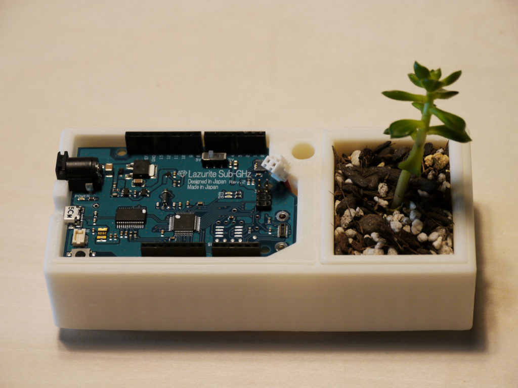
I designed the case so that the Lazurite circuit board and the plants come next to each other. At first I thought about making a more practical case, but I thought it would be nice to have an electronic circuit next to a plant.

Picture 5. Lazurite circuit board and the plant side by side
Now that Lazurite is set up on the case properly, we will build the circuit. First, let’s use the solar panel we created in “Using Arduino with Parts and Sensors – Solar Powered Arduino (part 3)” as the power source to power Lazurite. Lazurite uses much less electricity than Arduino Uno, so we don’t need too many solar panels. However, the maximum output voltage of 1 solar panel in this case is 5V. So when the weather isn’t so good, Lazurite may not function due to lack of voltage, so here, we started the test with the first 4, connected 2 solar panels in series at the end to get the required amount of voltage, then used a 3 terminal voltage regulator to get 5V.

Picture 6. Validating Lazurite using solar panels
Below is the circuit diagram. (Due to fritzing, the circuit board is an Arduino Uno, but please assume it is Lazurite)

Figure 2. Circuit diagram for Lazurite
Once you have finalized your circuit diagram, let’s move on to shielding. It’s been a while. Today, we will use Arduino’s proto shield (circuit board only) and solder the parts together.

Picture 7. Arduino proto shield
Using the circuit diagram, solder the parts together.

Picture 8. Soldering parts onto the proto shield circuit board

Picture 9. Solar panel mounted
Once you have soldered all the parts, check if everything works. If something doesn’t work at this point, it is possible that you did not successfully solder the parts. In that case, redo the process by using a solder extractor or a solder wick.

Picture 10. Testing the machine using a solar panel
Now that we know it works properly with solar panels, we will attach the remaining parts. First, attach the electric double layer capacitor (super capacitor), pump, and the soil sensor. For our improved watering machine, we used a small pump instead of a servomotor for the water supply, and a soil sensor instead of a nail to measure the water level in the soil. This sensor generally works for both analog and digital signals. We set it to analog, the same way we measured the water level when we were using a nail.

Picture 11. Building the circuit

Figure 3. Overview of the circuit diagram for the watering machine
Once the circuit part is complete, start mounting the remaining parts into the case. We designed a place to stick in the solar panel on top of the case, so that we could set the solar panels in a slanted position.

Picture 12. Setting up the shield and solar panel
Attach the soil sensor, and you’re done!

piture 13. The Lazurite watering machine is complete
We did it! We created a watering machine using Lazurite! In this edition we used a small case that fits on your desk, but you can get creative, like designing a case that can be attached to an existing pot, use a servomotor to supply water, and so on. Give it a shot! You can also use solar panels with more power or a bigger electric double layer capacitor (super capacitor) to make your machine more stable.
We printed the case for the watering machine using a 3D printer, but taking advantage of this opportunity, we also designed and printed out a special case for Lazurite Basic! With this, we no longer have to use the circuit board naked.

Picture 14. Lazurite Basic case

Figure 4. Modeling screen for Lazurite Basic case
Below is a link for the modeling data of the case we used. If you have a 3D printer and want to try it for yourself, please feel free to use it.
http://www.123dapp.com/MyCorner/akagawa_sh_…-26766851/models
 Using Arduino with Parts and Sensors – Solar Powered Arduino (part 3)
 Using Arduino with Parts and Sensors – Solar Powered Arduino (Part 1)
 How to Find Out When Your Plants Need Watering with a Soil Sensor
 Digital Vivarium Box Powered by Solar Panels Using Arduino (Part 2)
 Digital Vivarium Box Powered by Solar Panels Using Arduino (Part 1)
 The Basics of Arduino Electronics: Controlling the Motor