![]()

Pictures from WebIOPi public website.
There’s a lot of handy apps and tools out there, but since we want to make something ourselves, this time we’ll be using “WebIOPi” to operate GPIO with a browser.
I’m still a beginner with electronic kit components. Even the LED blink was like a fight to the death! I’ll break it into parts and thoroughly explain the process, starting from how to install WebIOPi! (By the way, our final objective here is acquiring analog values from a light sensor!)
WebIOPi is a software used to materialize the “IoT (Internet of Things)” with Raspberry Pi. It looks like it was published on Google Code before.
IoT (Internet of Things)
The Internet of Things (IoT) is the network of physical objects—devices, vehicles, buildings and other items—embedded with electronics, software, sensors, and network connectivity that enables these objects to collect and exchange data.
In WebIOPi’s case, input and output are performed with a browser. You can operate GPIO with a browser button, and likewise acquire values from GPIO and display them quite easily. The appeal in using a browser is that you can even easily modify web pages design with CSS and more!
Download last release – WebIOPi
First, let’s download the source file from the download page on their public website. This time, I’m using the version released on 2/10/2015, version which is the 0.7.1. Regarding Raspbian, I’m using the version released on 9/24/2015.
To install it, look for the ‘Installation’ page listed under ‘Tutorials’ in the top menu. The detailed command operations are even written down, so it’s easy to understand!
As a sample, I’ll introduce the three command lines below.
tar xvzf WebIOPi-x.y.z.tar.gz

cd WebIOPi-x.y.z

sudo ./setup.sh
Commands differ slightly depending on the environment, so I’ll detail these one at a time!
The first line is a command to unzip the downloaded file. We talked about the tar file in the article “Installing wordpress on Raspberry Pi”. With this command, since there are sometimes cases where there is a file in the same level as the current directory, be careful about your file path when you execute this command. Also, the “x.y.z” in the file name is where the version goes. Match it with the file you downloaded and then execute the command.
For Pi users, if you download from a browser, the file will be downloaded to the default /home/pi/Downloads/ folder,
tar xvzf /home/pi/Downloads/WebIOPi-0.7.1.tar.gz
So this time, let’s execute the command this way!

Figure 1
The unzipped file will be extracted in the current directory (in the above case, the /home/pi/ directory). There’s no problem with moving the file wherever you want (but this time we’ll keep the file at the same place).
If you’re using Raspberry Pi 2, you’ll need to edit the file.
TheWebIOPi version 0.7.1 doesn’t completely support Raspberry Pi 2. So before installing it, we need to overwrite two spots in the source code. Open the file in Notepad and edit the following:
WebIOPi-0.7.1/python/native/cpuinfo.c (Line 40)
Before Change
if (strcmp(hardware, "BCM2708") == 0)
After Change
if (strcmp(hardware, "BCM2709") == 0)
WebIOPi-0.7.1/python/native/gpio.c (Line 32)
Before Change
#define BCM2708_PERI_BASE 0x20000000
After Change
#define BCM2708_PERI_BASE 0x3f000000
In my case, I only noticed an issue after the installation. By re-executing setup.sh, I was able to install it without any problem. Future versions might improve this. Try to install it once to test, and then reinstalling if it’s not working. That might be the best way to go.
The second line is the cd command. This command moves you to the current directory, but make sure you execute it. The third line we’ll execute, setup.sh, won’t work properly if you’re not set to the current directory, so you need to be careful.
cd /home/pi/WebIOPi-0.7.1

sudo ./setup.sh
We’ve executed the commands this time, according to our environment. It’ll take a little time to install. We have to wait until the console stops.
Partway through, you’ll be prompted “Do you want to access WebIOPi over the Internet? [y/n]”, but it’s okay to select ‘n’ and skip that.
Once installation is complete, reboot Raspberry Pi once and start up WebIOPi!
sudo /etc/init.d/webiopi start
When starting up, it’s okay to just execute this one line.
When you want to manually stop, change ‘start’ to ‘stop’,
sudo /etc/init.d/webiopi stop
And execute like this.
On the public site, they’ve also introduced a command that automatically launches WebIOPi when Raspberry Pi starts up.
Command to Set Up Automatic Startup
sudo update-rc.d webiopi defaults
Command to Stop Automatic Startup
sudo update-rc.d webiopi remove
The settings will be applied after a reboot. Just by cutting the power to Raspberry Pi, you’ll be able to access a different console, making easy to use like Volumio, which we introduced last time!
First, let’s confirm things from the local environment on the Raspberry Pi. Access “http://localhost:800/” from the browser.

Figure 2
If WebIOPi has booted correctly, a username and password screen will be displayed. As it written on the public site, the default username is “webiopi” and the password is “raspberry”.

Figure 3
Here’s the WebIOPi main menu screen!
Four menus are displayed: “GPIO Header”, “GPIO List”, “Serial Monitor”, and “Devices Monitor”.
By the way, you’ll use the GPIO Header at the very top for the “LED Blink” we’re introducing this time.
You can switch IN/OUT, or switch output ON/OFF from the browser. But for some reasons, I couldn’t make it work on Raspberry Pi pre-installed Epiphany Web Browser or Midori. By using a PC, I could get the state of GPIO properly reflected. It might depend on the browser (expecting to try it on a future version!).
Since we’ve verified our local connection, let’s try accessing WebIOPi from a different PC next. From a PC connected to the same network, access the address “http://raspberrypi:8000/” from the browser. If you can’t access it, use the IP address instead of ‘raspberrypi’.
Just like local access, if the WebIOPi screen is displayed, you’ve successfully accessed it!
Now, let’s try operating GPIO from WebIOPi!

Figure 4
First, let’s work on the wiring for the electrical components. Like always, we’ll be wiring the LED. This time we’re going with a GPIO3 (5-pin).
Let’s get the Raspberry Pi ready. Here, all you have to do is starting up WebIOPi and you’re set.
sudo /etc/init.d/webiopi start
Once it’s ready, from a PC on the same network, access the address “http://raspberrypi:8000”! Click the ‘GPIO header’ link at the very top of the top menu, and open the screen as shown in Picture 5.

Figure 5
The Raspberry Pi GPIO displays graphically!
Here, the displayed pins go up to number 27. In Raspberry Pi terms, that’s up until the Raspberry Pi 1 Model B.

Figure 6
*If neither IN or OUT are displayed on the gray buttons on the left and right, WebIOPi may not be working properly. The each button state may be different depending on your environment.
You can also use a smartphone to operate GPIO, if it’s on the same network, of course. The hard part is, you can’t pinch the screen to zoom in on the display, so it’s a little hard to tap the buttons. I’d recommend you to access it with a large display smartphone or a tablet.
If you click the button above the display, you can operate CPIO from above the display.
The gray buttons to the left and right are buttons that direct the input and output GPIO state. By clicking them, you can select IN or OUT.
The buttons in the two central columns correspond to the GPIO pins. When they are in the OUT state, if you click the pin number’s number button, then you can switch HIGH/LOW.

Figure 7
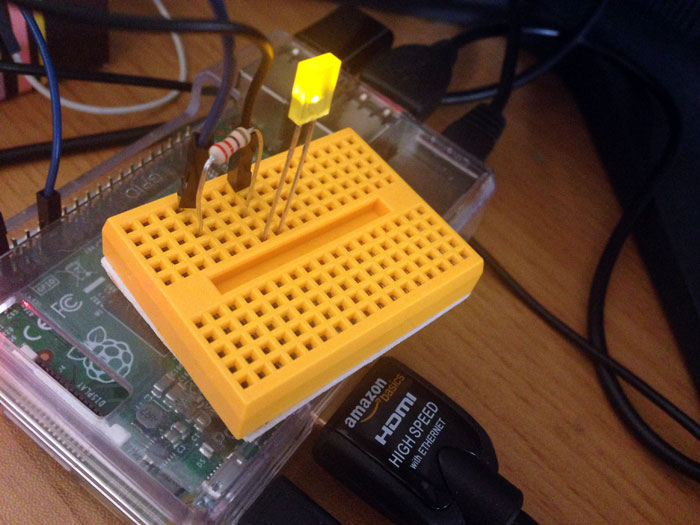
To light up an LED connected to the GPIO3 (pin 5), first we need to switch to OUT and set the output state.
Next, watch out for the number button! The button’s background color will switch. For HIGH output, the color displayed will be orange, and for LOW output, the color will be black. Just like switching input and output, you just have to click a button to switch HIGH/LOW.
When the GPIO settings is OUT and HIGH (orange), then the LED will light up.

Picture 1
Even when changing the pins position, we don’t have to restart to make it work.
You can also operate the same way from the GPIO List, second from the top on the main menu. Here, we have GPIO lined up in tandem.

Figure 8
The number on the button isn’t the pin number, but the pin name subscript. So ‘GPIO3’ isn’t 5, it’s 3. Its appearance looks like the GPIO Header page, and it’s easy to get it wrong, so be careful. Some pins like GND can’t be operated and have been omitted. So, this page is convenient to fully grasp which pins are in use.
Personally, I thought that the GPIO Header page, where you can see the pin alignment exactly as it is, was the easiest to handle.
Having succeeded making an LED blink, we’ll stop here for now.
While WebIOPi brings more convenience, we still have this unique handmade feeling from the electronic kit Even for those who don’t like command input, by using WebIOPi, you can start off your electronic kit more easily.
Of course, we only introduced a small part of WebIOPi. Next time, let’s move on from the default WebIOPi page, and customize each page!
 Making an LED Light up with Raspberry Pi Before Making It Blink
 Adding NAS Functionality to Raspberry Pi
 Raspberry Radio Part 1 – Internet Radio Receiver and Remote Access
 Introduction to Raspberry Pi 4: Tackling the Basic Electronic Kits With the Raspberry Pi 4!
 DIY Smart Picture Frame & Calendar Using Raspberry Pi 3 – PART 1
 Creating an AirPlay Network Audio Player with Volumio