![]()
Using Arduino with Parts and Sensors – Plant monitoring & watering device (with micro SD card)
In the last project, I used a micro SD card slot DIP kit to work with an SD card. This time, we will write values to a micro SD card and combine temperature sensor, light sensor, and new soil sensor to enable monitoring and watering a plant on my desk. Will this be helpful? Let’s build it and find out!

Expected time to complete: 120 minutes
Parts needed
Simultaneous communication with a micro SD card via the Ethernet shield
There are several ways to use a micro SD card in Arduino-based projects. If you want to minimize the work, you can connect to the regular SD card easily by using an SD card shield, Ethernet shield, Arduino wireless SD shield, or any other shield that has an SD slot mounted on it.
This time, we’ll use the micro SD card adapter on the Ethernet shield introduced when we created a web server with Arduino.
It is very convenient because the shield has a micro SD connector and can also communicate via LAN cable.

Figure 1: Arduino Ethernet shield
Set up the Ethernet shield as shown in the linked article. As noted in Diagram 1 below, there are certain pins that can only be used with the LAN adapter and not with the SD card. So, we will have to build our circuit in the other pins.

Figure 2: Usable pins on the Ethernet shield
Using the micro SD card via the Ethernet shield

Figure 3: A micro SD card mounted on the Ethernet shield
There are several differences from what we did in the previous article, using micro SD card on the Ethernet shield. The micro SD card’s Pin 2 is used for recording data and is connected to Pin 10 on the Arduino. This is aligned with Pin 4 on the Ethernet shield.
Micro SD pin specification:

Now, let’s program some codes!
These codes read data from the SD card.
|
1 2 3 4 5 6 7 8 9 10 11 12 13 14 15 16 17 18 19 20 21 22 23 24 25 26 27 28 29 30 31 32 33 34 35 36 37 38 39 40 41 42 43 44 45 46 47 48 49 50 51 52 53 54 55 56 57 58 59 60 61 |
#include <SPI.h> #include <SD.h> Sd2Card card; SdVolume volume; SdFile root; const int chipSelect = 4; // set to pin 4 if using Ethernet void setup() { Serial.begin(9600); while (!Serial) { ; // wait for serial port to connect. Needed for Leonardo only } Serial.print("\nInitializing SD card..."); pinMode(4, OUTPUT); // set to pin 4 if using Ethernet if (!card.init(SPI_HALF_SPEED, chipSelect)) { Serial.println("initialization failed. Things to check:"); Serial.println("* is a card is inserted?"); Serial.println("* Is your wiring correct?"); Serial.println("* did you change the chipSelect pin to match your shield or module?"); return; } else { Serial.println("Wiring is correct and a card is present."); } Serial.print("\nCard type: "); switch (card.type()) { case SD_CARD_TYPE_SD1: Serial.println("SD1"); break; case SD_CARD_TYPE_SD2: Serial.println("SD2"); break; case SD_CARD_TYPE_SDHC: Serial.println("SDHC"); break; default: Serial.println("Unknown"); } if (!volume.init(card)) { Serial.println("Could not find FAT16/FAT32 partition.\nMake sure you've formatted the card"); return; } uint32_t volumesize; Serial.print("\nVolume type is FAT"); Serial.println(volume.fatType(), DEC); Serial.println(); volumesize = volume.blocksPerCluster(); // clusters are collections of blocks volumesize *= volume.clusterCount(); // we'll have a lot of clusters volumesize *= 512; // SD card blocks are always 512 bytes Serial.print("Volume size (bytes): "); Serial.println(volumesize); Serial.print("Volume size (Kbytes): "); volumesize /= 1024; Serial.println(volumesize); Serial.print("Volume size (Mbytes): "); volumesize /= 1024; Serial.println(volumesize); Serial.println("\nFiles found on the card (name, date and size in bytes): "); root.openRoot(volume); root.ls(LS_R | LS_DATE | LS_SIZE); } void loop( void ) {} |

Figure 4: Confirmation of output on Serial Monitor
I was able to read the contents of the micro SD card via the Ethernet shield.
Recording data from the temperature and the light sensors
Now that we have the micro SD card set up, let’s record data from the temperature and the light sensors. If you’ve forgotten how to use the temperature or the light sensors, please refer back to this article where we make a Stevenson screen.
You can see the wiring diagram below:

Figure 5: Wiring diagram of temperature & light sensors connected to Ethernet shield

Figure 6: Circuits for temperature and light sensors
In the program, the data from the temperature and the light sensors is read using Analog Input and is written on the micro SD card. You set up the SD card using SD.open(“File name”, “Write mode”) from the Arduino SD card library. Once the file is open, the contents must be passed as a File variable and only then can reading or writing to the SD card occur. After all processing is complete, don’t forget to close the file with .close().
|
1 2 3 4 5 6 7 8 9 10 11 12 13 14 15 16 17 18 19 20 21 22 23 24 25 26 27 28 29 30 31 32 33 34 35 36 37 38 39 40 41 42 43 44 45 46 47 48 49 50 51 52 53 54 55 |
#include <SPI.h> #include <SD.h> const int chipSelect = 4; void setup() { Serial.begin(9600); while (!Serial) { ; // wait for serial port to connect. Needed for Leonardo only } Serial.print("Initializing SD card..."); pinMode(4, OUTPUT); if (!SD.begin(chipSelect)) { Serial.println("Card failed, or not present"); return; } Serial.println("card initialized."); } void loop() { String dataString = ""; for (int analogPin = 0; analogPin < 2; analogPin++) { int sensor = analogRead(analogPin); if (analogPin == 0) { dataString += String(sensor); dataString += ","; } else if(analogPin == 1){ dataString += String(modTemp(sensor)); } } File dataFile = SD.open("DATALOG.TXT", FILE_WRITE); // file name if (dataFile) { // confirms the SD card file was successfully opened (creates a new one if not) dataFile.println(dataString); // writes the contents from dataString dataFile.close(); //closes the file after writing data Serial.println(dataString); } else { Serial.println("error opening datalog.txt"); } } // convert the temperature sensor data to Celsius float modTemp(int analog_val){ float tv = map(analog_val,0,1023,0,5000); // convert the sensor data to voltage float temp = map(tv,300,1600,-30,100) ; return temp; } |

Figure 7: datalog.txt
I successfully wrote the data.
Now that we can write and read data from a micro SD card, let’s try to assemble a device!
Indoor plants need continuous care. Sometimes, watering your plants every day can get tedious. I’ve had numerous instances where I’d leave my plants and forget to water them for a long period of time and I would find my plants all droopy or even dead upon my arrival. Today, we’ll solve this problem by developing a watering machine!

Figure 8: A desk plant to be used for this tutorial
Deciding on the design for the plant monitoring device!
First, let’s figure out the design of the device. We want to reduce the burden of watering plants so it’d be nice to have a soil sensor to detect when the soil is dry and automatically water the plant. Also, I want to read values from the temperature and the light sensors simultaneously and record them together on the SD card. We can also predict when the flowers will start blooming based on the accumulated temperature data. We can write a program that will make flower blooming predictions based on the data stored in the SD card. To summarize, we want to:
Now, it’s time to build a device that will do these two things.
Making the soil sensor
First, let’s build a soil sensor to measure the soil’s dryness. There are prefabricated Arduino-compatible soil humidity sensors but we’re going to try something simpler in this article. The Arduino-compatible soil humidity sensor has two metal prongs that record a resistance value, which is the sensor reading. If the moisture content of the soil is high, current flows easily and the resistance value is low. Conversely, if the soil is dry, there is less electrical flow so the resistance value is high. When you understand this setup, you can test the this principle with 2 nails rather than using a special sensor.
*If you’re going to use this setup for a long period of time, iron nails will rust and the resistance value will change. In such case, it’s better to use the Arduino-compatible soil humidity sensor or rust proof nails.

Figure 9: A DIY soil sensor made of 2 nails
Connect 2 nails to the conductive wires. These can be on the same circuit as the light sensor.

Figure 10: Wiring diagram of temperature, light, and soil sensors

Figure 11: Nails placed in soil
First, connect to Analog Pin 2 and read the soil sensor’s value with Analog Input. Next, fill the pot halfway with water. You can see that the value that was at 900-1000 lowers to around 600.

Figure 12: Soil sensor readings
Since the resistance value drops as you add water, you can use these readings to determine the maximum resistance value. Again, high resistance value means the soil is dry. You can test and see what values you get by adding water.
Implementing the watering system
There are various ways to water your plants but I’ve used one that is simple and cost-effective. We can design a system that uses a simple pump nozzle from a bottle with a servo attached. It will be designed so that the servo will pump out the water by pressing the nozzle (Figure 14).
If you have a large plant that requires a lot of water, you can use a battery-powered oil pump. Depending on the size of your plant, there are all sorts of options you can try.

A $1 bottle with pump spray nozzle

Figure 14: Servo-driven watering system
I bought 3 types of shampoo bottles to try. Since the servo I’m using isn’t very powerful, the servo failed to press down on two of the shampoo bottle nozzles. If your servo is weak, you can try to supply power from a separate battery and see if that works.
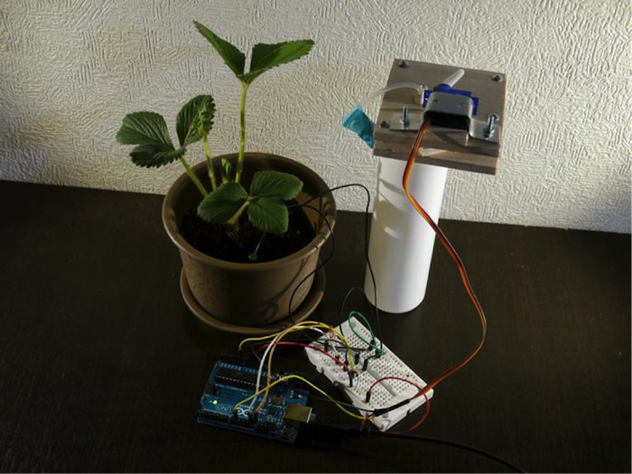
After much travail, I finally managed to put my watering system together (Figure 15).

Figure 15: Completed plant monitoring device

Figure 16: Plant monitoring device circuit
Lastly, we need to write a program so we can save the soil sensor readings and water the plant whenever necessary. I set up a rule to pump 5 times whenever the resistance of the soil sensor is or above 700.
|
1 2 3 4 5 6 7 8 9 10 11 12 13 14 15 16 17 18 19 20 21 22 23 24 25 26 27 28 29 30 31 32 33 34 35 36 37 38 39 40 41 42 43 44 45 46 47 48 49 50 51 52 53 54 55 56 57 58 59 60 61 62 63 64 65 |
#include <SPI.h> #include <SD.h> #include <Servo.h> const int chipSelect = 4; Servo myservo; int pos = 0; int sensorValue = 0; // variable to store the value coming from the sensor int sensorPin = A0; void setup() { myservo.attach( 9 ); Serial.begin(9600); while (!Serial) { ; // wait for serial port to connect. Needed for Leonardo only } Serial.print("Initializing SD card..."); pinMode(4, OUTPUT); if (!SD.begin(chipSelect)) { Serial.println("Card failed, or not present"); return; } Serial.println("card initialized."); } void loop() { String dataString = ""; for (int analogPin = 0; analogPin < 3; analogPin++) { int sensor = analogRead(analogPin); if (analogPin == 0) { //光センサの値 dataString += "Light:"; dataString += String(sensor); dataString += ",Temp:"; } else if(analogPin == 1){ //温度センサの値 dataString += String(modTemp(sensor)); dataString += ",Ground:"; } else if(analogPin == 2){ //soil sensor value sensorValue = analogRead(sensorPin); dataString += String(sensorValue); // pump 5 times whenever the soul resistance value is above 700 if(sensorValue > 700){ for(int u=0;u<5;u++){ pos = 180; myservo.write( pos ); delay(1500); pos = 0; myservo.write( pos ); delay(1500); pos = 180; myservo.write( pos ); } } } } File dataFile = SD.open("datalog.txt", FILE_WRITE); if (dataFile) { dataFile.println(dataString); dataFile.close(); Serial.println(dataString); } else { Serial.println("error opening datalog.txt"); } } // Change the temperature sensor value to Celsius float modTemp(int analog_val){ float tv = map(analog_val,0,1023,0,5000); // Change the sensor value to voltage float temp = map(tv,300,1600,-30,100) ; return temp; } |
If you have any comments or questions, please leave them for us at Google +. Follow us there; we will be posting more soon.
 How To Make Parking Assist Car Sensors
 Arduino Sensors – ROHM Sensor Evaluation Kit Overview
 Arduino Bluetooth Gloves Part 1 – Basics
 Innovation Success Factors from the Creator of Rapiro
 Smart Garden System using Arduino Create + ROHM Sensor Evaluation Kit
 Score A Wealth Of Soccer Data From This Startups Eagle Eye


