![]()
As I promised, the rest of this article will be a step-by-step guide to help you make the robot on your own! If you’re only interested in the final result, feel free to skip to the last page. And for the rest of you, let’s get to work! The drawings of all the parts are available on my GitHub in PDF. If you decide to print them, do it without margins, so that the drawings remain in the original 1:1 scale. All the dimensions are in millimeters.
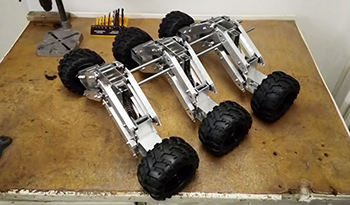
Before we get started, I just want to clarify the terminology here. I am not a mechanical engineer. I have no idea what most of these parts would be properly called in English (or in any other language for that matter), so I made up my own names for stuff. Use the following picture as a reference for what I mean when I talk about “motor block”, “suspension block” or “frame block”.

Figure 6. Terminology reference
Now is probably time to obtain all the materials. Some of the parts like motors and wheels were already listed in the Hardware requirements in the beginning, so here I will only focus on the aluminum profiles and bolts. Also, all the dimensions in the following tables are in millimeters and all the bolts are M-type – the ones with a hexagonal head.
Aluminium profiles
| Part Number & Name | Profile type | Width | Height | Wall Thickness | Length | Count |
| [1] Control arm | U profile | 30 | 15 | 2 | 180 | 24 |
| [2] Suspension block | Square tube | 40 | 20 | 2 | 100 | 6 |
| [3] Motor block | Square tube | 80 | 50 | 3 | 50 | 6 |
| [4] Frame block | Square tube | 80 | 40 | 2 | 100 | 3 |
| [5] Absorber attachments | U profile | 25 | 25 | 2 | 80 | 12 |

Figure 7. All the types of used aluminium profiles
Nuts and bolts
| Part Number & Name | Length | Count |
| [1] M3 bolt | 8 | 36 |
| [2] M3 bolt | 30 | 6 |
| [3] M3 nut | – | 18 |
| [4] M4 bolt | 22 | 6 |
| [5] M5 bolt | 8 | 48 |
| [6] M5 bolt | 12 | 96 |
| [7] M5 nut | – | 144 |
| [8] M7 bolt | 30 | 6 |
| [9] M7 nut | – | 12 |
| [10] M8 nut | – | 48 |
| [11] M10 nut | – | 12 |

Figure 8. All the types of used nuts and bolts