![]()
Similarly to the way we made the controls arms, we will also make the suspension and motor blocks. We need the holes in these two parts to align perfectly, so we will clamp and later bolt them together. These are probably the most difficult parts to make, so be extra careful when measuring the holes.

Figure 11. Drawing of the suspension block (scale 1:1)

Figure 12. Drawing of the motor block (scale 1:1)
3.1 First of all, you have to mark the spots for all the holes in the suspension block. We’ll be drilling through it, so it is enough to make the markings on one side only. Just as we did before, measure out everything, punch a guide with nail and a hammer and drill small 2.50 mm holes.

3.2 Next, we’ll enlarge the holes that will hold the bearing axes. I recommend doing this in two steps: first, drill a 5 mm hole all the way through the part – into the opposing wall – so that the final holes will be aligned. Only then drill the 8 mm holes.

3.3 Now we need to clamp together the suspension block and the motor block so that holes for the bolts that will hold them together are aligned. Make sure that the edges of both blocks are aligned and that the suspension block is in the middle of the motor block.

3.4 Now enlarge two of the small holes with 5 mm drill bit. Drill all the way through the opposite wall of the suspension block and through the top wall of the motor block.

3.5 Remove the clamps and bolt the blocks together with two M5 bolts. Again, it is extremely important that the edges of both the blocks are well aligned. Then, drill the other two holes with a 5mm bit. After that, remove the bolts and knock down the burrs inside the motor block. Now you have a motor block and a suspension block that will fit together very precisely. Just as with the control arms, I suggest marking them so that you know which ones fit together when we start assembling the robot.

3.6 The last thing that the suspension block is missing are holes for the absorber attachment. We drilled them with 2.50 mm bit earlier, so now just enlarge them to 6 mm. Be careful to only drill through one wall of the suspension block! When that is done, the suspension block is finished and you can set it aside for now.

3.7 Take the motor block and mark two of the six front holes that will be used to mount the motor itself. Then, drill the marked holes with 3 mm drill bit.

3.8 Next, we have to drill the other four holes to mount the motor. Aligning these is pretty difficult, but we have a trick up the sleeve: the Pololu 37D mount. That has all the holes drilled in it already! So we can bolt it to the motor block with a couple M3 bolts, and now we have a sort of template through which we can drill.

3.9 Drill the remaining 4 holes with 3 mm drill bit.

3.10 Remove the template and enlarge the holes with 4 mm drill bit. Some of the holes probably aren’t aligned well enough so we can cheat a bit and add 1 mm of extra wiggle room.

3.11 Measure and drill a hole for the motor axis to go through. Be extremely careful and precise when making measurements for this hole! Start with 3 mm bit and gradually enlarge the hole to the 12 mm diameter we need. Still, you will probably need to correct this hole with a round file a little bit until you get a nice fit for the motor.

3.12 Last step here is to file down the corners of the motor block so that it doesn’t interfere with the wheel movement. Just a few millimeters should be enough, you can test by mounting the motor and then attaching the wheel to it. If it runs smoothly, you’re good to go!

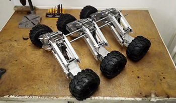
Do the whole thing six times and you can move on the next part. I promise you that all the hard stuff is done and from this point on, it will be a breeze.
We’re not quite done yet! We will be adding absorbers to the frame the suspension blocks we just made. Then we’ll finally put every component together and assemble the chassis!