![]()
Since our robot will be moving around in a natural environment, it would be pretty cool if it had some onboard sensors to measure all sort of properties of its surroundings. For this purpose, I’m using ROHM Sensor Evaluation Kit which makes sensing the physical world a lot easier. Arduino libraries for the individual sensors can be downloaded from the links below. In this project, I’ll be using the following sensors:
There’s a slight catch though – all the sensors were designed to be used when inserted into the headers on the shield. Since the shield will be closed off inside the sealed box, some sensors like the UV radiation sensor will not really measure anything sensible. Furthermore, sensors like accelerometer and magnetometer have to be physically mounted to a stable platform, but when they are merely inserted to the shield, they tend to move back and forward quite a lot. This would seriously affect the measurements done with these sensors.
The solution to all these problems is fairly simple. We just need some enclosure for the sensors. Something that can be easily mounted to any part of the chassis, something that will provide sufficient cover but won’t block the environmental property we’re trying to measure. That’s why I designed these little covers for all the sensors I’m using. They can be easily printed on any 3D printer. More info about them can be found in a separate article: 3D Cases for ROHM Sensor Evaluation Kit.

Figure 4. Sensor covers
Another part that needs some sort of cover is the camera. We also want to position the camera, and that’s what the 9g servos are for. Originally, I wanted to use one of the cheap camera mounts you can find online. That turned out to be a waste of about 5 dollars since the mount snapped in half the first time I accidentally hit it. Rather than trying my luck with another one, I designed and 3D printed my own! It’s much sturdier than the first one, and we should be able to get some pretty decent pictures with it.

Figure 5. The camera mount
All the files for this model are available on Thingiverse, so if you need a compact and sturdy camera mount for any project, feel free to 3D print this one!
Of course, all of these sensors and the camera have to be mounted somewhere. I decided to mount them atop the front frame block, on a square piece of 3 mm acrylic plate. We will then run the cables from the sensors into the electronics box that is placed directly behind them.

Figure 6. Sensor mount detail without the camera. The captions show which sensor is in a given case

Figure 7. Sensors and camera mounted in the final place
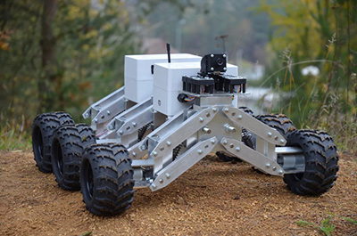
The final tweak you might have to do is to change the toughness of the suppressors. Since I decided to use a massive lead-acid battery, most of the weight will be placed on the last pair of suspension. To compensate for that, I set the last pair of suppressors to the toughest setting, the first to the softest and the center one to about middle.

Figure 8. The suppressor on the toughest setting (top) and the softest setting (bottom)
This step depends on the exact battery you decide to go with. If your battery is light enough, It might not even be necessary to change the suppressor toughness. However, my battery is huge: it has 8.5 Ah capacity, and weighs 2.7 kg (5.95 lbs). This is kind of a trial-and-error step, so just put the battery on the chassis and tinker with the settings for a while to see what works best for your setup. Ideally, the chassis should be level when it’s standing on a flat surface – it shouldn’t be tilted forward or backward.