Step 8: Wiring the logic side
Now comes the most challenging part of this entire article: wiring the logic side, the sensors and the Arduino together. Even though we are using two shields (LoRenz shield and ROHM Sensor Evaluation Shield), there’s quite a lot of modules to connect. Here’s a Fritzing diagram of the wiring. Please note that the ROHM shield isn’t shown in the diagram, since it would cover most of the other connections.

Figure 9. Fritzing diagram of the logic side wiring
Kind of a mess, isn’t it? All of the components are powered from the Arduino 5V regulator, with an exception of the motor drivers, which are powered directly from the battery. That is also the power source for the Arduino itself. With that out of the way, let’s take a look at all the important connections separately. I recommend connecting the modules one at a time and testing each new connection you make.
-
- Servos. Their signals are connected to Arduino pins 8 and 9, which support PWM (pulse width modulation).
- LoRenz shield. The shield uses SPI bus. Unfortunately, on Arduino Mega this bus is located on pins 50, 51 and 52. The shield was designed with Arduino UNO in mind, so it assumes SPI is on the pins 13, 12 and 11. We can get around that by directly connecting pins on the U/M header on the shield to the corresponding pins on Arduino Mega. Also, the Slave Select pin will remain in the default position (pin 7).
- SD card module. Just as the LoRenz shield, this module uses SPI bus. So we can just connect it to pins 50, 51 and 52 and some generic digital pin which will act as Slave Select, right? Well, it’s not that easy. Our Arduino has 5V logic – this means that voltage level 5V (with some tolerance) is interpreted as logic 1, while voltage 0V (again, there is quite a bit of tolerance) is seen as logic 0. The wireless module used by LoRenz has 3.3V logic, but this is properly converted to 5V to allow reliable communication with Arduino. The SD card module also has 3.3V logic, however, it is only converted in one direction (since that is cheaper to manufacture). This means that all the signals coming out of the module are still 3.3V logic. This makes the communication on the bus very unreliable, or it downright breaks it. The moral of the story is, if you’re dealing with different logic levels on a bus that might have more than two devices on it, ALWAYS properly convert them and don’t mix different voltage levels on one bus.
Fortunately, SPI communication is so simple it can be done by software. So we can just connect the SD module to any three digital pins and then handle it in code. The pins I chose are 13, 12 and 11.
- VC0706 camera. The camera is connected using RS-232 (Serial) bus. Once again, the camera has 3.3V logic. Since only two devices can be connected to RS-232 at a time, just a simple voltage divider on the Arduino RX line will be enough. The camera is using the third hardware serial line available on the Mega on pins 16 and 17 (Serial2 in Arduino code).
- GPS module. This is the second module that uses serial line, so we can place on the fourth serial port (Serial3) pins 14 and 15. I intentionally left out the second port (Serial1), because pins 18 and 19 have interrupts on them, and we will need those for the sensors.
- ROHM Sensor shield. This shield is on the top of the LoRenz shield. Here, we have to connect the sensors and the interrupts. I have the sensors connected as the following:
| Sensor Name |
Shield Slot |
| BM1422GMV |
I2C_1 |
| KX022-1020 |
I2C_2 |
| RPR-0521RS |
I2C_4 |
| BM1383GLV |
I2C_5 |
| BD1020HFV |
ANALOG_1 |
| ML8511A |
ANALOG_2 |
Because interrupt pins 2 and 3 are already used by LoRenz, we can’t simply select them by shorting some pins on the shield (for more information on how interrupts work on the ROHM Sensor shield, please refer to RohmMultiSensor wiki). BM1422GMV is in the slot I2C_1, which is connected to INT1. So, we’ll connect INT1 to Arduino pin 18, which has interrupt support. Similarly, KX022-1020 is in the slot I2C_2, connected to INT3, which we will connect to Arduino pin 19.
- VNH5019 motor drivers. These don’t require any special bus to connect, just two digital pins to control the direction, one PWM pin to control the speed and one optional analog pin to read the current passing through the motors. The left side driver is connected to pins 41, 43, 45 (PWM) and A15 (analog), and the right side to pins 40, 42, 44 (PWM) and A14 (analog).
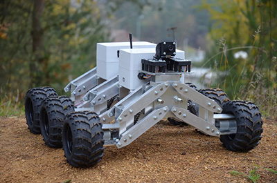
Did you make it this far? Great, because that was the most difficult part of this article! When you’re done wiring, you should end up with something that looks a little bit like this:

Figure 10. All the electronics connected