![]()
Table of Contents
1. Introduction
1.1 Practical radio for Makers
1.1.1 Frequency
1.1.2 Antennas
1.1.3 Power
1.1.4 Space
1.2 What you will learn
2. Arduino garage opener and universal radio interface
2.1 Arduino garage opener, base station
2.1.1 BOM
2.1.2 Power up!
2.2 Arduino garage opener, handheld unit
2.2.1 BOM
2.2.2 Power up!
Incidental radio waves are everywhere. Deep space echoes from the Big Bang are most evident in the microwave spectrum, whereas the rather local echoes from your in-house electrical wiring, and nearby metro train system, are most evident at 50-60Hz. Whenever you’re touching a 3.5mm TRS jack and hear that aggravating hum, it’s you being a big audible condenser for incidental analog radio waves.
In this article, we’ll go over a practical and interference robust radio system perfectly suited for Makers.
It’s suitable for both analog and digital transmission and reception. It has CRC checksums. It’s flexible with regard to where on the ISM/SRD bands (433 and 902-928MHz are commonly used in the US, it’s also capable of 868MHz) you want to be and allows reprogramming so you can use the frequency that is right for you and what’s allowed in your country. For concerns about legality, see this FCC REGULATIONS FOR LOW-POWER, UNLICENSED TRANSMITTERS resource, part 15.231, Intermittent Control Signals.
With regard to range, it’s a big step up from WiFi, but nowhere near as long-range as LoRa. Expect 400 meters in a Line-of-Sight (LOS) scenario with a directional antenna on both stations.
Whenever, for instance, kBaud is mentioned in the CC1101 datasheet, think 0.125kByte. In fact, just think of baud as bits, so 8 bits per byte. There’s a difference, most notably with Manchester and 4-FSK encoding, but this is highly irrelevant to our Arduino Garage Opener & Universal Radio Interface.
The most important factors in radio applications are arguably frequency (measured in hertz, Hz), power (measured in watts, W), antennas and space.
Let’s briefly cover each.
1.1.1 Frequency
Frequency, Hertz (kilohertz, megahertz, gigahertz) describes the periodic interval, or cycles per second, of a particular thing. If a pendulum completed one full swing in precisely one second, it would have a frequency of 1Hz.
If it took two seconds, it would have a frequency of 0.5Hz, and for two swings per second, it would be 2Hz. But we are interested in electromagnetic radiation here, and for EM waves, the same principle applies.
The speed of light, “c”, is 299.792.458m/s, but for the sake of simplicity, it is popularly “just” 300.000km/s. Knowing both the speed of light and frequency, we intrepidly divide the speed of light with frequency “f” in megahertz, and derive wavelength (lambda, or “l”). Just so:
|
1 2 3 4 |
c / f = l 300 / 433 = 0.692 |
Multiply the result “l” by 100 to get the wavelength in centimeters, and (100/2.54) to get the wavelength in inches.
Knowing both the speed of light and the wavelength, we divide “c” with “l” and learn the value of “f.” Thus:
|
1 2 3 4 |
c / l = f 300 / 0.6928 = 433.02 |
1.1.2 Antennas
That’s all the math we’ll need. This is easy to remember, and all you need to work with various frequencies and DIY antennas.
Our CC1101 modules will be set for 433MHz operation, and have onboard SMA connectors. Note that the CC1101 can operate in the ranges 300-348 MHz, 387-464 MHz and 779-928 MHz. The included antennas are curiously only 4cm/1.57in long. Though they may be coil antennas underneath the insulation, I nevertheless call these antennas sixteenth-wave antennas and expect not so much from them.
Fortunately, using the above formulas, we can construct perfectly good quarter-wave whip antennas. For SMA antennas like mine, the rubber insulation can be removed and a quarter-wave coil antenna can be soldered on. Practically speaking, a 433MHz signal would fit nicely with a wire having a length of:
|
1 2 3 |
300/433/4 = 0.173 |
That is 17.3cm/6.18in. The lengths for quarter-wave antennas are similarly easy to calculate, just divide the results for wavelength by 4. For antennas, using either stranded or solid-core wire is fine, as long as it is insulated, but solid-core is easier to coil. It’s the electrical length that matters, and a 17.3cm/6.18in antenna on a tiny little handheld garage opener is annoying.
1.1.3 Power
Signal strength is also important and is described as dB-millivolts per meter (dBmV/m), or dB-microvolts per meter (dBuV/m), OR decibels exceeding one milliwatt (dBm). You’ll need a frequency counter placed directly next to an antenna to read this accurately — I usually concern myself only with the mW/W value and see how far I can ping and get some pong back, just like a submarine!
Our CC1101 radio modules read about 30mV on my frequency counter, which is decent (and leads me to speculate they’re 3.3×0.03=100mW), but setting a transmitter up for continuous transmission, and doing a range test outside, I only start losing signal at ~60m/197ft. Great!
If you’re interested in learning more about dBm, which is the correct way to approach radio signal strength, see the Wikipedia page on dBm. It’s pretty cool.
1.1.4 Space
Space is, in layman’s terms, distance, and whatever is in the space between two points.
In space, there could be a tree, a forest, a house or just tiny atmospheric particles, such as water molecules. If the space is clear, radio waves propagate neatly from Point A to Point B. If the space is littered with metal bits, the waves get mangled and scattered.
We can expect our radio signal to dissipate and scatter just by traversing distance, and hitting obstacles (even leaves on trees are insurmountable obstacles to long-range WiFi PtP links) just makes it harder to transmute the transmitted “ping” to a resounding “pong.”
I’m extremely pleased to inform you that the CC1101 radios take these problems away. 433MHz is pretty crowded these days, so ~60m/197ft is an extremely good range for reliable digital transmissions in a MODERN URBAN ENVIRONMENT, spammed with interference and lots of obstacles.
Once you’ve read this article, you will know how to run your Arduino alongside
CC1101 radios connected via SPI.
SPI from Arduino 5V to 3V3 logic level requires level shifting, so you’ll either learn that or degrade/burn out your hardware. I bet you’ll learn it.
You’ll also already have learned practical radio baboonery, such as relevant formulas for calculating wavelengths (for antennas) and frequency from wavelengths. This makes it easy for you to make any kind of antenna you need. Antennas are the most overpriced copper wires in the world, but not for you.
If you didn’t already know this, you’ll learn how to debounce input signals (from tactile switches/pushbuttons) with moderate confidence. However, this can be so ugly code-wise that a really good alternative is using a 10K potentiometer on one of the ADC pins. Faster too (10 uS per reading), if your code has no time to debounce — and now you learned that.
When your builds (there are two) are complete, you will be able to transmit and receive control/telemetry over longer ranges than, for instance, WiFi trivially allows, as well as perform relevant operations on your byte streams. The “magic_token” variable in “ArduinoGarageOpener_CC1101.ino” can safely be grown to 32 or 64 bytes. It doesn’t really seem to affect the rate of transmission errors much.
When you expand the Garage Base Station segments in the code, you’ll learn how to use less memory quite organically.
When your code breaks away from defined behaviour, because you’ve pulled too much SRAM into use (there is only 2KB on atmega328p), just send a happy “foo!” over the Arduino Serial Monitor, and see how much memory you have remaining. If you get nothing back, revert your most recent changes.
H-bridges (for shifting polarity/direction on DC motors) will be mentioned, and you’ll learn enough about them to know if you want to build one. To haunt your dreams, I will briefly show & tell an H-bridge. It’s still running somewhere in the house, but I never liked it. For you, I’ll find it.
If you like super-fast, direct manipulation of the Arduino’s port registers, H-bridges can be great fun. More on that in section 2!
2. Arduino garage opener & universal radio interface
Garage openers operate with a big, hefty motor. They come in all shapes and sizes, from humble 12V to almost-high-voltage 48V and beyond. What’s interesting is, how do you interface with it? It depends. You’ll need to pop open the box and have a look-see inside.
Bipolar motors intended to operate in two directions are fairly simple to take over. Just remove the drive circuitry until you’re left with the motor itself, the power supply, and the box, of course.
The Arduino Motor Shield (Rev3) isn’t up to the task (in fact, avoid all things L298N) — you’ll need a more powerful motor driver, such as the SHIELD-MD10, rated for 7-30V, 10A.
Or build your own H-bridge and drive it with direct Arduino port manipulation. Here’s a pictorial diagram of what that can look like:

See my notes for port manipulation below. It’s not so bad that you gotta feel sad:
|
1 2 3 4 5 6 7 8 9 10 11 12 13 14 15 16 17 18 |
Atmega328p Ports register reference: Port D 1 2 3 4 5 6 7 8 -- -- -- -- -- -- -- -- D7 D6 D5 D4 D3 D2 D1 D0 Port B 1 2 3 4 5 6 7 8 --- --- --- --- --- --- --- --- D13 D12 D11 D10 D9 D8 Port C 1 2 3 4 5 6 7 8 -- -- -- -- -- -- -- -- A5 A4 A3 A2 A1 A0 |
… And some example code from my hoard …
|
1 2 3 4 5 6 7 8 9 10 11 12 13 14 15 16 17 18 19 20 21 22 23 24 25 26 27 28 29 |
// setup() // Set D8+D9+D10+D11+D13 as OUTPUTs DDRB = 0b00101111 ; // Set all bits in register LOW PORTB = 0b00000000 ; // ... // Functions that belong elsewhere void bridgeOFF( void ) { // Set all output pins LOW PORTB = 0b00000000 ; // Motor Spin-down grace period delay( 300 ) ; } void bridgeForward( void ) { bridgeOFF() ; // Forward, D8+D9+D13 HIGH, D13 is the onboard LED. PORTB = 0b00100011 ; } void bridgeReverse( void ) { bridgeOFF() ; // Reverse, D10+D10 HIGH, D13 is set LOW here. PORTB = 0b00001100 ; } |
Totally doable and very cheap. Get it wrong, though, and a single shoot-through of pure *oomph* will blow either one or both electric paths. H-bridges must be timed precisely.
The H-bridge in the diagram can be seen below, and despite the fact it uses outdated BJTs, it performs flawlessly. Lost, but found again.

Regardless, the motor driver is yours to decide on (hint: SHIELD-MD10!), and will vary depending on the garage setup. Now on to the Arduino garage opener itself!
Firstly, if you’re unfamiliar with the Arduino IDE, read this first.
Download the Arduino IDE from the official Arduino website, and learn how to install a library here.
The library we’re interested in is included in this zip file, ArduinoGarageOpener_CC1101.
But for your convenience, it can be browsed/downloaded on Github or installed directly with “git” into your Arduino libraries folder, like so:

Onward!
Our library, Arduino_CC1101, contains two examples for transmitting and receiving.

Refer to these if you find the main program overwhelming; these examples are really simply put together.
We have one program file, ArduinoGarageOpener_CC1101.ino, and it contains the
code for both the garage opener and the garage base station. These lines determine the functionality of your compiled Arduino firmware. Set the constant
“IS_GARAGE_OPENER” to 1 if you wish to compile for the handheld unit, and “IS_GARAGE_STATION” to 0.
For the garage base station, set the constant “IS_GARAGE_STATION” to 1, and “IS_GARAGE_OPENER” to 0.
Press CTRL+R to compile, and CTRL+U to (compile and) upload. Both the program and the relevant library are to be found in the zip file “ArduinoGarageOpener_CC1101“.
|
1 2 3 4 5 6 |
// Handheld unit? #define IS_GARAGE_OPENER 0 // Garage base station? #define IS_GARAGE_STATION 1 |
| Arduino Nano | https://www.newark.com/arduino/a000005/dev-board-atmega328-arduino-nano/dp/13T9275 |
| CC1101 RF module | https://www.elecrow.com/433mhz-rf-transceiver-cc1101-module-p-374.html |
| ROHM SLR343BC4TT32 3mm LED | https://www.digikey.com/product-detail/en/rohm-semiconductor/SLR343BC4TT32/SLR343BC4TT32-ND/2337159 |
| 330ohm resistor | https://www.newark.com/multicomp-pro/mccfr0w4j0331a50/carbon-film-resistor-330-ohm-250mw/dp/58K5042 |
| Dupont wires | https://www.newark.com/multicomp-pro/mccfr0w4j0331a50/carbon-film-resistor-330-ohm-250mw/dp/58K5042 |
| Breadboard | https://www.newark.com/multicomp-pro/mccfr0w4j0331a50/carbon-film-resistor-330-ohm-250mw/dp/58K5042 |
| 3.3+5V power supply | https://www.newark.com/bud-industries/bbp-32701/breadboard-power-supply-5v-3-3v/dp/56AC7832 |
| Level Shifter | https://www.newark.com/adafruit/395/logic-level-converter-8ch-arm/dp/53W5916 |
Follow the wiring in the pictorial diagram below.

Observe the power of the Fritzing pictorial-diagram software! While the CC1101 8P header is poorly drawn (pictorially, at least), you must still level shift. The CC1101 will run decently if you don’t do it, but for how long?
The code:
|
1 2 3 4 5 6 7 8 9 10 11 12 13 14 15 16 17 18 19 20 21 22 23 24 25 26 27 28 29 30 31 32 33 34 35 36 37 38 39 40 41 42 43 44 45 46 47 48 49 50 51 52 53 54 55 56 57 58 59 60 61 62 63 64 65 66 67 68 69 70 71 72 73 74 75 76 77 78 79 80 81 82 83 84 85 86 87 88 89 90 91 92 93 94 95 96 97 98 99 100 101 102 103 104 105 106 107 108 109 110 111 112 113 114 115 116 117 118 119 120 121 122 123 124 125 126 127 128 129 130 131 |
/* Constants from Arduino_CC1101/ELECHOUSE_CC1101.h: Name Pin Comment SCK_PIN 13 MUST LEVELSHIFT FROM Arduino 5V to CC1101 SPI 3V3! MISO_PIN 12 MOSI_PIN 11 MUST LEVELSHIFT FROM Arduino 5V to CC1101 SPI 3V3! SS_PIN 10 CSN/SS; MUST LEVELSHIFT FROM Arduino 5V to CC1101 SPI 3V3! GDO0 2 GDO2 9 */ // Handheld unit? #define IS_GARAGE_OPENER 0 // Garage base station #define IS_GARAGE_STATION 1 #if IS_GARAGE_OPENER // Interrupt/sleep related libraries, not used. //#include <avr/wdt.h> //#include <avr/interrupt.h> //#include <avr/sleep.h> //#include <avr/power.h> //const byte wakePin = 3 ; // INT1 #elif IS_GARAGE_STATION // Motor open/close drive times usually differ, // time both separately with a stopwatch app. #define motor_open_drive_time 100 // ms, change this #define motor_close_drive_time 100 // ms, change this #endif #include const byte buttonPin = 6 ; bool buttonState = LOW ; bool previousButtonState = LOW; unsigned long previousDebounceTime = 0 ; //unsigned long debounceDelay = 50; unsigned long debounceDelay = 100 ; const int magic_token_len = 6 ; // PING LIKE A SUBMARINE! byte magic_token[ magic_token_len ] = { "PING!" } ; const int input_buffer_len = 6 ; const byte ledPin = 4 ; bool is_garage_open = false ; // 0: No Serial.printing, except in serialEvent() // 1: Lots of useful information, such as received data, events etc. const bool debug = 1 ; void setup( void ) { Serial.begin( 115200 ) ; pinMode( ledPin, OUTPUT ) ; ELECHOUSE_cc1101.Init( F_433 ); // Frequency: 433MHz //ELECHOUSE_cc1101.Init( F_868 ) ; // Frequency: 868MHZ //ELECHOUSE_cc1101.Init( F_915 ) ; // Frequency: 915MHz if ( IS_GARAGE_STATION ) ELECHOUSE_cc1101.SetReceive() ; // Do listen else if ( IS_GARAGE_OPENER ) { // 10K pull-down from D6->GND, then D6->SW1->5V pinMode( buttonPin, INPUT ) ; } } void loop( void ) { // Begin Garage Opener if ( IS_GARAGE_OPENER ) { int read = digitalRead( buttonPin ) ; if( read != previousButtonState ) { // Reset the debouncing timer previousDebounceTime = millis() ; } if ( (millis() - previousDebounceTime ) > debounceDelay ) { if ( read != buttonState ) { buttonState = read ; // Still HIGH? if (buttonState == HIGH) { digitalWrite( ledPin, HIGH ) ; Serial.println( "[!] Sending magic_token three times ..." ) ; // Now send magic_token with moderate confidence for ( int it = 0 ; it < 3 ; it++ ) { ELECHOUSE_cc1101.SendData( magic_token, magic_token_len ) ; } delay( 50 ) ; digitalWrite( ledPin, LOW ) ; } } } previousButtonState = read ; } // End Garage Opener // Begin Garage Station else if ( IS_GARAGE_STATION ) { byte input_buffer[ input_buffer_len ] = { 0 } ; bool token_matched = false ; if ( ELECHOUSE_cc1101.CheckReceiveFlag() ) { int len = 0 ; len = ELECHOUSE_cc1101.ReceiveData( input_buffer ) ; if ( debug ) { Serial.print( F( "[!] RX data => " ) ) ; Serial.println( (const char *)input_buffer ) ; Serial.print( F( "[!] RX data length => " ) ) ; Serial.println( len, DEC ) ; } delay( 100 ) ; // Are magic_token and input_buffer identical? if( strncmp( (const char *)magic_token, (const char*)input_buffer, 2 ) == 0 ) { token_matched = true ; // If open, close // If closed, open // set is_garage_open accordingly } else token_matched = false ; // End token_match // Begin open/close actions if ( token_matched ) { if ( is_garage_open ) { if( debug ) Serial.println( F( "[!] Garage door CLOSE action!" ) ) ; // Drive closed ... is_garage_open = false ; digitalWrite( ledPin, LOW ) ; delay( motor_close_drive_time ) ; } else if ( ! is_garage_open ) { if ( debug ) Serial.println( F( "[!] Garage door OPEN action!" ) ) ; // Drive open ... is_garage_open = true ; digitalWrite( ledPin, HIGH ) ; delay( motor_open_drive_time ) ; } } // End open/close actions } ELECHOUSE_cc1101.SetReceive() ; // Do continue listening } } // Called if Arduino receives data over serial link void serialEvent( void ) { printFreeRAM() ; while ( Serial.available() > 0 ) Serial.read() ; } // Print free SRAM in bytes void printFreeRAM( void ) { extern int __heap_start, *__brkval ; int v ; v = (int) &v - (__brkval == 0 ? (int) &__heap_start : (int) __brkval ) ; Serial.print( F( "[!] Free RAM => " ) ) ; Serial.println( v, DEC ) ; } |
When powered up, the base station will start listening for “magic_token”, which is “PING!” It could be anything, you decide.
When it receives the correct byte sequence (which currently consists of the ASCII codes for “P”, “I”, “N”, “G”, “!” presumably transmitted with ASK modulation), it will trigger “OPEN”/”CLOSE” events for whatever you wish. A motor driver like the SHIELD-MD10, an H-bridge, relays.
For the “OPEN” and “CLOSE” actions, there’s a delay. We’re assuming it takes two different periods of time to respectively open and close a garage door. That’s the why of it.
Play around with the constants “motor_open_drive_time” and “motor_close_drive_time” until it’s right. An alternative is using hall effect sensors, but that’s not covered here.
|
1 2 3 4 |
#define motor_open_drive_time 5000 // ms #define motor_close_drive_time 5000 // ms |
We track the current state with the variable “is_garage_open”, so we can close when open, and
vice versa. It is only stored in SRAM, not EEPROM.
Particularly important for the base station is to remember, when you’re adding your motor drive code, do pay attention to free SRAM in the serial monitor (CTRL+SHIFT+M) by sending a “foo!” to your Arduino. There are 1823 bytes free in the current setup, but that can quickly change if you include some fancy library.
When the “OPEN” action is triggered, the ROHM 3mm LED will be lit up. If the variable “debug” is true, you can track activity over the Arduino Serial Monitor, see below.

2.2 Arduino garage opener, handheld unit
Press the button to send “magic_token”.
2.2.1 BOM
| Arduino Nano | https://www.newark.com/arduino/a000005/dev-board-atmega328-arduino-nano/dp/13T9275 |
| CC1101 RF module | https://www.elecrow.com/433mhz-rf-transceiver-cc1101-module-p-374.html |
| ROHM SLR343BC4TT32 3mm LED | https://www.digikey.com/product-detail/en/rohm-semiconductor/SLR343BC4TT32/SLR343BC4TT32-ND/2337159 |
| 330ohm resistor | https://www.newark.com/multicomp-pro/mccfr0w4j0331a50/carbon-film-resistor-330-ohm-250mw/dp/58K5042 |
| Dupont wires | https://www.newark.com/multicomp-pro/mccfr0w4j0331a50/carbon-film-resistor-330-ohm-250mw/dp/58K5042 |
| Breadboard | https://www.newark.com/multicomp-pro/mccfr0w4j0331a50/carbon-film-resistor-330-ohm-250mw/dp/58K5042 |
| 3.3+5V power supply | https://www.newark.com/bud-industries/bbp-32701/breadboard-power-supply-5v-3-3v/dp/56AC7832 |
| Level Shifter | https://www.newark.com/adafruit/395/logic-level-converter-8ch-arm/dp/53W5916 |
| 10kOhm resistor | https://www.newark.com/arcol/mra0207-10k-b-15ppm-ta/res-10k-0-10-250mw-axial/dp/79Y4556 |
| Pushbutton | https://www.newark.com/adafruit/1119/tactile-switch-pcb-breadboard/dp/84X1201 |
We’re using the same code as for the base station, only change the constants “IS_GARAGE_OPENER” to 1 and “IS_GARAGE_STATION” to 0.
Once again, follow the wiring in the pictorial diagram below.

The momentary switch requires debouncing. How much depends on your locale; a noisy desk with a power supply connected to mains will require more than a handheld floating battery-powered unit. Try setting the variable “debounceDelay” to 40-50ms. We’re connecting pin D6 -> pushbutton -> 5V, but require a pull-down resistor near D6. Like so: D6 -> 10kOhm -> GND.
The handheld unit operates as a generic garage opener (albeit highly overpowered). Your choice of battery pack can conveniently be a USB power bank if using the Arduino Nano.
If you’re intrepid and use an Arduino Pro Mini 3V3 (atmega168), you can use a TP4056(+DW01) battery module along with a 3.7V lipo battery. That would make the level shifter unnecessary as well. For battery longevity, the Arduino sleep mode you want is “SLEEP_MODE_PWR_DOWN”. Your call.
When the pushbutton is pressed and the debounce delay confirms it is indeed pressed, and not just affected by jitter, it will proceed to send the contents of the “magic_token” variable through the CC1101 radio.
If your base station is in range and powered up, it will catch the transmission, and an “OPEN”/”CLOSE” action will take place.
At the very end of things, you may see something like this on your desk.
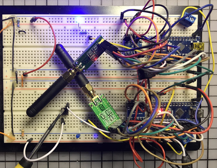
Don’t despair. Shortened jumper wires would have helped, as would separate breadboards. But the main point is really to test if it works, and it works really well.
The range test was, of course, done with a big cluster of wires, the Arduino and CC1101 in hand, all running from a USB battery pack with a step-down for the 3V3 rail, blinking and blinking, confirming that indeed the glorious “PING!” was received.
Bear in mind that these two builds can be used as a template to control any kind of electronics over radio — it’s not strictly limited to operating a garage door. Other hardware, such as Raspberry Pis, can be present on either end, if you need an easy way to send telemetry without messing up your Raspbian installation. The program is written specifically to let you easily adapt it to any kind of application.
Go forth and interface!
 Let’s Play with ESP-WROOM-32 on Arduino (Bluetooth-BLE Connection)
 Using Arduino with Parts and Sensors – Accelerometer Part 2
 How To Shrink Your Projects For Arduino
 Arduino Robot RF Explorer – Mechanics – Part 1
 Build A Robot with Arduino
 Intro to RTL-SDR for AM/FM, ISM band, LoRa transmission, and satellite tracking


