![]()
Click here to read Part 1 of this Article>

In Part 1, we discussed several important steps in building an explorer robot. We designed and created our own PCBs using Eagle. In Part 2, we will be adding the rest of the parts and test the program to make sure that the RF robot functions the way it’s supposed to. The explorer robot we design here will be able to travel autonomously, sense its surroundings, and transmit the collected data wirelessly. The goal of this project is to prototype an explorer robot, equipped with a set of sensors such as temperature and pressure, which will be able to send collected information in real time with the help of digital radio communication modules (RF).

Figure 1: RF Robot Setup from Part 1
The remote will take information from laptop’s USB port and redirect it via the second nRF24l01+ module. It will be composed of the Arduino board and a board with NRF connector and supply which will be mounted above the Uno to avoid using wires.

Figure 2: The remote schematic

Figure 3: Remote PCB

Figure 4: The remote with NRF24L01+ mounted connected to Arduino Uno
You will see that we incorporated two LEDs which signal the circuit’s functionality and the other components discussed above. We’ll include little coolers for overheating protection for the voltage regulator and the NPN transistor as well. The circuit board will be positioned above the batteries as shown below in Figure 5.

Figure 5: The remote mounted above the batteries
We’re using nRF24L01+ wireless transceiver module. nRF24L01+ is an ultra low power wireless RF transceiver. Using this module is the best choice when it comes to such an application. It is one of the most popular models because of its great performance and cheap price. Its common communication protocol enabled it to gain a huge global software support.
Specifications:

Figure 6: NRF24L01+ module
To obtain pressure and temperature data, we’ll use a Sparkfun BMP085 barometric pressure sensor. It offers measurement from 300 to 110 kPa with an error of 0.03 kPa. BMP085 also provides a temperature measurement from 0 to 65 °C. The supported voltage must not exceed the interval 1.8-3.6V and the connection is made directly with the microcontroller by l2C.
Specifications:

Figure 7: BMP085 barometric pressure sensor
Now we will mount HC-SR04 ultrasonic sensor. HC-SR04 has detection range of 2-200 cm. The microcontroller sends an impulse to the sensor which emits sound wave. When the sensor knows that the wave has returned it sends an impulse back to the microcontroller. This calculates the difference between when the impulse was sent and the moment the impulse is received and thus calculates the distance:
?=(?2−?1)×170

Figure 8: HC-SR04 distance sensor placed at the front of the chassis
The Arduino platform provides predefined functions which spares the user of configuring some registers. There are libraries that allow interfacing the platform with many other peripherals. The programming is done in a very simple way with a single Arduino-PC cable. The board comes equipped with a USB-UART converter.
In this project, two programs are needed: one for the robots functioning and another for the remote. The two programs communicate with one another by radio with the help of nRF24101+ module. The data flow diagram is shown in Figure 9. There are two ways. Direct way: First, the information is being sent by the application to Arduino. Then the information taken over by the transceiver is further sent down to the second transceiver and then back to the microcontroller. This takes decisions for the control of the physical movement of the robot.

Figure 9: Data flow diagram
Reverse way: the controller takes the information from the sensors and processes them and sends them to OTA (on the air) in order for them to finally reach PC.
The application was done with Microsoft Visual Studio 2010 using the Visual C# programming language. Having a very intuitive interface, Visual Studio combines the visual elements with the programming part. This helps achieve some very complex applications. The application sends commands and receives data which are then displayed. The robot controller is done with the help of the keyboard arrows. The movement buttons light up as you press an arrow to indicate that the command was received. These commands are actually letters transmitted in serial that are meant to reach the robot controller to be interpreted. For example, when you press the “Up” key, the application sends “U” on the serial port by USB. The interpretation table of the commands is shown below:
| Letter | Action |
| U | Go on |
| R | Turn right |
| D | Move backward |
| L | Turn left |
| N | Update |
| B | Turn on the lights |
| O | Send PWM value |
To achieve this we have implemented the following algorithm: the application sends the LED “turn on” command and then the remote control takes the command and sends it to the robot. Once the robot receives the command, it turns on the LEDs and sends an instruction to the application to turn on the light indicators. We have introduced this algorithm to avoid desync (the case in which the LEDs are off and the indicator is on).
Another important issue was the import and display of information in the interface. To make the application differentiate the information and know where to display it, we have implemented the following method: Once the robot receives information from the remote control, it does not simply forward it but it processes it and sends commands as follows: “CMD: TE =” + val.marime. The application will know that once retrieved an information that starts with “CMD” through the serial port should remove “:” and read the following two letters that refer to the field where the information will be written. The “val. marime” is read after “=” and for the above example, the program will know how to assign it to the temperature field.
In order to make the application recognize two simultaneous key presses we have initialized a variable for each key. When a key is pressed, the event increments its variable to 1; when it released another, the event decrements it to 0. A timer continually evaluates these variables.

Figure 10: Design the application
This time the robot uses a program compiled in Arduino IDE, having greater complexity than the remote control program:
1. The remote
|
1 2 3 4 5 6 7 8 9 10 11 12 13 14 15 16 17 18 19 20 21 22 23 24 25 26 27 28 29 30 31 32 33 34 35 36 37 38 39 40 41 42 43 44 45 46 47 48 49 50 51 52 53 54 55 56 57 58 59 60 61 62 63 64 65 66 67 68 69 70 71 72 73 74 75 76 77 78 79 80 81 82 83 84 85 86 87 88 89 90 91 92 93 94 |
#include <SPI.h> #include "nRF24L01.h" #include "RF24.h" char cmd[3]; RF24 radio(9,10); const uint64_t pipes[2] ={ 0xE8E8F0F0E1LL, 0xDEDEDEDEE7LL} ; float bar[7]; char arc[3]; int cifra[3]; int val; int a; void setup(void){ Serial.begin(9600); radio.begin(); radio.openWritingPipe(pipes[0]); radio.openReadingPipe(1,pipes[1]); radio.setDataRate(RF24_250KBPS); pinMode(6, OUTPUT); pinMode(5, OUTPUT); } void loop(void){ if(Serial) { digitalWrite(6, HIGH); digitalWrite(5, LOW); } else { digitalWrite(5, HIGH); digitalWrite(6, LOW); } cmd[0]=Serial.read(); if(cmd[0]=='O') { delay(20); arc[0]=Serial.read(); delay(20); arc[1]=Serial.read(); delay(20); arc[2]=Serial.read(); //Storing the values cifra[0]=arc[0]-'0'; cifra[1]=arc[1]-'0'; cifra[2]=arc[2]-'0'; val=10*cifra[0]+cifra[1]; Serial.println(val); Serial.println(sizeof(cmd)); cmd[0]='X'; cmd[1]=val; cmd[2]=cifra[2]; radio.write(cmd, sizeof(cmd)); } a=1; if(cmd[0]=='N') { radio.write(cmd, sizeof(cmd)); radio.startListening(); delay(1); while(a==1) { if (radio.available()){ a=2; bool done = false; while (!done){ done = radio.read(bar, 28); Serial.print("CMD:X1="); Serial.println(bar[0]); delay(5); Serial.print("CMD:D1="); Serial.println(bar[1]); delay(5); Serial.print("CMD:TE="); Serial.println(bar[2]); delay(5); Serial.print("CMD:PR="); Serial.println(bar[3]); delay(5); Serial.print("CMD:AT="); Serial.println(bar[4]); delay(5); Serial.print("CMD:AL="); Serial.println(bar[5]); Serial.print("CMD:LE="); Serial.println(bar[6]); } } } } else { radio.write(cmd, sizeof(cmd)); } } |
2. The robot
|
1 2 3 4 5 6 7 8 9 10 11 12 13 14 15 16 17 18 19 20 21 22 23 24 25 26 27 28 29 30 31 32 33 34 35 36 37 38 39 40 41 42 43 44 45 46 47 48 49 50 51 52 53 54 55 56 57 58 59 60 61 62 63 64 65 66 67 68 69 70 71 72 73 74 75 76 77 78 79 80 81 82 83 84 85 86 87 88 89 90 91 92 93 94 95 96 97 98 99 100 101 102 103 104 105 106 107 108 109 110 111 112 113 114 115 116 117 118 119 120 121 122 123 124 125 126 127 128 129 130 131 132 133 134 135 136 137 138 139 140 141 142 143 144 145 146 147 148 149 150 151 152 153 154 155 156 157 158 159 160 161 162 163 164 165 166 167 168 169 170 171 172 173 174 175 176 177 178 179 180 181 182 183 184 185 186 187 188 189 190 191 192 193 194 195 196 197 198 199 200 201 202 203 204 205 206 207 208 209 210 211 212 213 214 215 216 217 218 219 220 221 222 223 224 225 226 227 228 229 230 231 232 233 234 235 236 237 238 239 240 241 242 243 244 245 246 247 248 249 250 251 252 253 254 255 256 257 258 259 260 261 262 263 264 265 266 267 268 269 270 271 272 273 274 275 276 277 278 279 280 281 282 283 284 285 286 287 288 289 290 291 292 293 294 295 296 297 298 299 300 301 302 303 304 305 306 307 308 309 310 311 312 313 314 315 316 317 318 319 320 321 322 323 324 325 326 327 328 329 330 331 332 333 334 335 336 337 338 339 340 341 342 343 344 345 346 347 348 349 350 351 352 353 354 355 356 357 358 359 360 361 362 363 364 365 366 367 368 369 370 371 372 373 374 375 376 377 378 379 380 381 382 383 384 385 |
#include <SPI.h> #include "nRF24L01.h" #include "RF24.h" #include #define BMP085_ADDRESS 0x77 // I2C address of BMP085 #define trigPin 2 #define echoPin 4 const unsigned char OSS = 0; int pwm, test1, test2; char cmd[3]; RF24 radio(9,10); const uint64_t pipes[2] ={ 0xE8E8F0F0E1LL, 0xDEDEDEDEE7LL} ; float bar[7]; int ac1; int ac2; int ac3; unsigned int ac4; unsigned int ac5; unsigned int ac6; int b1; int b2; int mb; int mc; int md; float temperature, pressure, atm, altitude,leduri; long b5; void bmp085Calibration() { ac1 = bmp085ReadInt(0xAA); ac2 = bmp085ReadInt(0xAC); ac3 = bmp085ReadInt(0xAE); ac4 = bmp085ReadInt(0xB0); ac5 = bmp085ReadInt(0xB2); ac6 = bmp085ReadInt(0xB4); b1 = bmp085ReadInt(0xB6); b2 = bmp085ReadInt(0xB8); mb = bmp085ReadInt(0xBA); mc = bmp085ReadInt(0xBC); md = bmp085ReadInt(0xBE); } // Calculate temperature in deg C float bmp085GetTemperature(unsigned int ut){ long x1, x2; x1 = (((long)ut - (long)ac6)*(long)ac5) >> 15; x2 = ((long)mc << 11)/(x1 + md); b5 = x1 + x2; float temp = ((b5 + 8)>>4); temp = temp /10; return temp; } // Calculate pressure given up // calibration values must be known // b5 is also required so bmp085GetTemperature(...) must be called first. // Value returned will be pressure in units of Pa. long bmp085GetPressure(unsigned long up){ long x1, x2, x3, b3, b6, p; unsigned long b4, b7; b6 = b5 - 4000; // Calculate B3 x1 = (b2 * (b6 * b6)>>12)>>11; x2 = (ac2 * b6)>>11; x3 = x1 + x2; b3 = (((((long)ac1)*4 + x3)<<OSS) + 2)>>2; // Calculate B4 x1 = (ac3 * b6)>>13; x2 = (b1 * ((b6 * b6)>>12))>>16; x3 = ((x1 + x2) + 2)>>2; b4 = (ac4 * (unsigned long)(x3 + 32768))>>15; b7 = ((unsigned long)(up - b3) * (50000>>OSS)); if (b7 < 0x80000000) p = (b7<<1)/b4; else p = (b7/b4)<<1; x1 = (p>>8) * (p>>8); x1 = (x1 * 3038)>>16; x2 = (-7357 * p)>>16; p += (x1 + x2 + 3791)>>4; long temp = p; return temp; } // Read 1 byte from the BMP085 at 'address' char bmp085Read(unsigned char address) { unsigned char data; Wire.beginTransmission(BMP085_ADDRESS); Wire.write(address); Wire.endTransmission(); Wire.requestFrom(BMP085_ADDRESS, 1); while(!Wire.available()) ; return Wire.read(); } // Read 2 bytes from the BMP085 // First byte will be from 'address' // Second byte will be from 'address'+1 int bmp085ReadInt(unsigned char address) { unsigned char msb, lsb; Wire.beginTransmission(BMP085_ADDRESS); Wire.write(address); Wire.endTransmission(); Wire.requestFrom(BMP085_ADDRESS, 2); while(Wire.available()<2) ; msb = Wire.read(); lsb = Wire.read(); return (int) msb< } // Read the uncompensated temperature value unsigned int bmp085ReadUT(){ unsigned int ut; // Write 0x2E into Register 0xF4 // This requests a temperature reading Wire.beginTransmission(BMP085_ADDRESS); Wire.write(0xF4); Wire.write(0x2E); Wire.endTransmission(); // Wait at least 4.5ms delay(5); // Read two bytes from registers 0xF6 and 0xF7 ut = bmp085ReadInt(0xF6); return ut; } // Read the uncompensated pressure value unsigned long bmp085ReadUP(){ unsigned char msb, lsb, xlsb; unsigned long up = 0; // Write 0x34+(OSS<<6) into register 0xF4 // Request a pressure reading w/ oversampling setting Wire.beginTransmission(BMP085_ADDRESS); Wire.write(0xF4); Wire.write(0x34 + (OSS<<6)); Wire.endTransmission(); // Wait for conversion, delay time dependent on OSS delay(2 + (3<<OSS)); // Read register 0xF6 (MSB), 0xF7 (LSB), and 0xF8 (XLSB) msb = bmp085Read(0xF6); lsb = bmp085Read(0xF7); xlsb = bmp085Read(0xF8); up = (((unsigned long) msb << 16) | ((unsigned long) lsb << 8) | (unsigned long) xlsb) >> (8-OSS); return up; } void writeRegister(int deviceAddress, byte address, byte val) { Wire.beginTransmission(deviceAddress); // start transmission to device Wire.write(address); // send register address Wire.write(val); // send value to write Wire.endTransmission(); // end transmission } int readRegister(int deviceAddress, byte address){ int v; Wire.beginTransmission(deviceAddress); Wire.write(address); // register to read Wire.endTransmission(); Wire.requestFrom(deviceAddress, 1); // read a byte while(!Wire.available()) { // waiting } v = Wire.read(); return v; } float calcAltitude(float pressure){ float A = pressure/101325; float B = 1/5.25588; float C = pow(A,B); C = 1 - C; C = C /0.0000225577; return C; } int distance2() { long duration, distance; digitalWrite(trigPin, LOW); // Added this line delayMicroseconds(2); // Added this line digitalWrite(trigPin, HIGH); delayMicroseconds(10); // Added this line digitalWrite(trigPin, LOW); duration = pulseIn(echoPin, HIGH); distance = (duration/2) / 29.1; if (distance < 4) { // This is where the LED On/Off happens } else { } if (distance >= 200 || distance <= 0){ } else { } return distance; } void setup(void){ pinMode(trigPin, OUTPUT); pinMode(echoPin, INPUT); bar[0] ='A'; Serial.begin(9600); radio.begin(); radio.openReadingPipe(1,pipes[0]); radio.openWritingPipe(pipes[1]); radio.startListening(); radio.setDataRate(RF24_250KBPS); pwm=255; pinMode(5, OUTPUT); pinMode(6, OUTPUT); pinMode(7, OUTPUT); pinMode(8, OUTPUT); pinMode(2, OUTPUT); pinMode(4, INPUT); pinMode(3, OUTPUT); Wire.begin(); bmp085Calibration(); } void mersF(int timp, int pwm) { analogWrite(5, pwm); digitalWrite(6, LOW); digitalWrite(8, LOW); digitalWrite(7, LOW); delay(timp); digitalWrite(5, LOW); } void mersS(int timp, int pwm) { analogWrite(6, pwm); digitalWrite(5, LOW); digitalWrite(8, LOW); digitalWrite(7, LOW); delay(timp); digitalWrite(6, LOW); } void VirareD(int timp, int pwm) { analogWrite(5, pwm); digitalWrite(6, LOW); digitalWrite(8, HIGH); digitalWrite(7, LOW); delay(timp); digitalWrite(5, LOW); digitalWrite(8, LOW); } void VirareS(int timp, int pwm) { analogWrite(5, pwm); digitalWrite(6, LOW); digitalWrite(7, HIGH); digitalWrite(8, LOW); delay(timp); digitalWrite(7, LOW); digitalWrite(5, LOW); } void VirareDspate(int timp, int pwm) { analogWrite(6, pwm); digitalWrite(5, LOW); digitalWrite(8, HIGH); digitalWrite(7, LOW); delay(timp); digitalWrite(6, LOW); digitalWrite(8, LOW); } void VirareSspate(int timp, int pwm) { analogWrite(6, pwm); digitalWrite(5, LOW); digitalWrite(7, HIGH); digitalWrite(8, LOW); delay(timp); digitalWrite(7, LOW); digitalWrite(6, LOW); } void stop(){ digitalWrite(5, LOW); digitalWrite(6, LOW); digitalWrite(7, LOW); digitalWrite(8, LOW); } void trimitere() { temperature = bmp085GetTemperature(bmp085ReadUT()); //MUST be called first pressure = bmp085GetPressure(bmp085ReadUP()); atm = pressure / 101325; // "standard atmosphere" altitude = calcAltitude(pressure); //Uncompensated caculation - in Meters leduri=digitalRead(3); radio.stopListening(); bar[0]=analogRead(A2); bar[1]=distance2(); bar[2]=temperature; bar[3]=pressure; bar[4]=atm; bar[5]=altitude; bar[6]=leduri; radio.write(bar, sizeof(bar)); delay(200); radio.startListening(); } void aprindere() { if(digitalRead(3)) digitalWrite(3,LOW); else digitalWrite(3,HIGH); delay(30); } void loop(void){ if (radio.available()){ bool done = false; while (!done){ done = radio.read(cmd, 3); if (cmd[0] == 'U'){ Serial.println("Exec cmd: Up"); mersF(30,pwm); } else if (cmd[0] == 'E'){ Serial.println("Exec cmd: Right"); VirareD(30,pwm); } else if (cmd[0] == 'C'){ Serial.println("Exec cmd: Right"); VirareDspate(30, pwm); } else if (cmd[0] == 'Z'){ Serial.println("Exec cmd: Right"); VirareSspate(30,pwm); } else if (cmd[0] == 'D'){ Serial.println("Exec cmd: Down"); mersS(30,pwm); } else if (cmd[0] == 'Q'){ Serial.println("Exec cmd: Left"); VirareS(30, pwm); } else if (cmd[0] == 'N'){ delay(30); trimitere(); } else if (cmd[0] == 'B'){ delay(30); aprindere(); } else if (cmd[0] == 'J'){ stop(); delay(30); } else if (cmd[0] == 'X'){ test1=cmd[1]; test2=cmd[2]; pwm=test1*10+test2; delay(30); } else { } } } } |
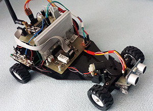
Figure 11: Complete RF robot

Figure 12: Assembled RF robot (side view)
Now we have built an autonomous arduino robot that is capable of self-navigating and collecting data from the surrounding environment! It was quite challenging but very rewarding project. The prototype can be further improved such as including housing case for protection in rough terrains/environments. Please feel free to share with me if you have any suggestions for further improvement!
 Arduino Robot RF Explorer – Mechanics – Part 1
 Make a Laser Arduino Robot Using Parallax Laser Sensor – Part 2
 3D Cases for ROHM Sensor Evaluation Kit and RohmMultiSensor Library Update
 Smart Garden System using Arduino Create + ROHM Sensor Evaluation Kit
 Make an LED Arduino Christmas Tree with ROHM Sensor Kit
 Make a Laser Arduino Robot Using Parallax Laser Sensor – Part 1