![]()
In today’s article, we will deliver a new plan for electronic kits using Arduino divided into Part 1 and Part 2. This unique electronic kit will be introduced by Makoto Hirahara, an artist whose body of work focuses on the theme of relationships. Mr. Hirahara, an associate professor at Osaka University of Arts, has produced a lot of media art using computers and electronic devices. In recent years, he’s been turning his attention in making 3D works using natural materials such as wood and stone. So please enjoy today’s edition.
In this article, I would like to introduce an example that uses the power of the sun. This piece allows you to observe digital creatures that are generated by solar panels and expressed through LEDs. First, check out this video. The green dots represent grasses, which are generated by the sun, and other dots are animals that eats the grasses. The animals reproduce themselves when they are full, or you can generate them by knocking the device.
Would any of you happen to know what a Vivarium is? It’s a word that not many people may be familiar with. Vivarium is a horticultural style in which plants and small animals are placed in glass containers where they are bred in a way that is close to the natural environment. Originally, it was started in order to carry animals and plants alive from a remote place by reproducing the environment where they lived. Later on, it become popular for decoration.

In the electronic kit that I’ll be introducing this time, I would like to reproduce the vivarium mechanism that allows living creatures to live by external light energy by using solar panels and an LED matrix. The grass grows little by little in the 5 x 5 LED space. Animals move toward the most outgrown grass. Moving it will drain a certain amount of health and die when it reaches 0. Entering a thicket of grass, animals that eat the feed will increase their physical strength. If an animal exceeds the upper limit, animals of the same color will then increase. If the number of animals increases too much, the number of plants will also decrease, meaning the animals will not be sustainable, so balance is important to maintain the ecosystem.

General sketch of the idea
Let’s start with a diagram of the overall device structure.
The power supply uses solar panels, the microcomputer board is the easy-to-use and compact Arduino Pro Mini 328, while the display device uses a full-color serial LED tape that is easy to wire. Also, since just looking at it isn’t enough, an accelerometer is also used to operate the water tank with your finger.

Individual parts are selected based on the overall structure. Since it is necessary to adjust the balance for each part, we’ll decide from an option that has little room.
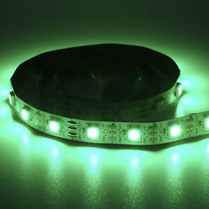
There are a variety of shapes such as cannonball type and surface mount available, but we decided to use a full-color serial LED tape because it is easy to wire, very expressive and easy to control. To arrange in a grid, cut it into five pieces and connect the five pieces together.

Full color serial LED tape
To make it portable, we will use a compact Arduino that can be inserted into a breadboard with peripheral circuits. There are two types of Arduino Pro Mini 328, 5V and 3.3V, but we’ll be using the 5V type because the power supply voltage of the full-color serial LED tape is 5V.

Arduino Pro Mini 328(5V 16MHz}
For the same voltage, the current increases as the area increases. We have selected the ones that can supply 5V and above, can light up the LEDs and are just the right size to carry.

OPL55A27101(5.5V 270mA
Many accelerometers are 3.3V, but the Arduino Pro Mini 328 does not have a 3.3V output, so I looked for one that could operate at 5V. When using a 3.3V sensor, lower the voltage with a three-terminal regulator.

Adafruit LIS3DH Triple-Axis Accelerometer
| Part Name(Where to Purchase URL) | # of Parts | Price |
| Arduino Pro Mini 328 5V 16MHz | 1x | $9.95 |
| Full Color Serial LED Tape | 1x | $24.95 |
| FTDI USB Serial Conversion Adapter | 1x | $14.00 |
| DC Jack(breadboard compatible) | 1x | $0.95 |
| Breadboard | 1x | $5.90 |
| DC Plug Inner Diameter 2.1mm Outer Diameter 5.5mm | 1x | $9.99 |
| Solar Panel | 1x | $5.95 |
| Accelerometer Adafruit LIS3DH | 1x | $4.95 |
| Soft Jumper Wire | 10x | $4.99 |
| Hard Jumper Wire | 10x | $10.99 |
| Pan Head Screws M2×12mm | 8x | |
| Basswood Plywood 600mm x 300mm Diameter 3mm | 1x | |
| Semitransparent Acrylic Board 120mm x 120mm Diameter 1mm | 1x |
Price as of writing. Shipping is not included.
Wiring Diagram and Circuit Diagram
Today we’ll be producing the wiring diagram and circuit diagram for this piece. Equipped with Arduino Pro Mini 328 and accelerometer, DC jack on breadboard. If the straight jumper wires on the breadboard are hard, they can be wired neatly. To attach the yellow and green jumper wires to the Arduino Pro Mini 328 pin header, we’ll be using the male-female type. A full-color serial LED tape is attached to the exterior, so connect it with a long soft jumper wire. Since the solar panel also serves as a cover for the outside, a DC plug is attached to the lead wire for easy wiring.
The circuit diagram shows the electrical connection relationship, while the wiring diagram takes into account the actual size and positional relationship. If you aren’t used to it, it may be easier to create a wiring diagram as it is, but it’ll probably be easier to understand when you are used to producing and making your own circuits or incorporating other people’s circuits.

Wiring diagram

Circuit diagram
Step 1:Soldering the Pin Header
Solder the attached pin header to a board such as Arduino Pro Mini 328. Be careful not to mistake the mounting direction.
Arduino Pro Mini 328
Solder the 12 x 2 rows of pins on the long side of the board on the component mounting surface; six pins on the short side while SDA and SCL are soldered on the side where the logo is printed.

Accelerometer
Solder all pins on the component mounting side.

DC Jack
Solder the pin header and DC jack to the board. The DC jack is fixed into place with a little more solder.

Step 2:Attaching DC Plug onto the Solar Panel
Solder the DC plug onto the tip of the solar panel lead. Disassemble the DC plug and pass the lead wire through the plastic tube. Remove the film from the tip of the lead wire and soak the solder a little. Place solder on the DC plug bracket in advance. Solder the minus (black) lead wire to the longer (outer) of the bracket and the plus (red) lead to the shorter (center).

Step 3:Temporary Wiring for Full Color Serial LED tape
Temporary wiring for testing is performed on the full-color serial LED tape. Cut the jumper wire connector and remove about three millimeters of the coating. Soak the solder a little into the exposed copper wire. Solder the end of the full-color serial LED tape (the base side of the arrow). Be careful not to apply too much heat, as the tape substrate will be deformed.

Step 4:Assemble the Breadbox
Lay out the Arduino Pro Mini 328 according to the wiring diagram. The wiring from the full-color serial LED tape and the jumper wires that connect the Arduino Pro Mini 328 and the SDA and SCL of the accelerometer are soft, while the other is hard.

Since the circuits are finished, let’s try testing out each of the parts’ functions.
Reading Arduino Pro Mini 328
The USB serial conversion adapter used this time has a function to switch the operating voltage. Since the Arduino Pro Mini 328 with a power supply voltage of 5V is used, install a jumper pin on the 5V side.

Connect the USB cable to the USB serial conversion adapter and connect your PC and Arduino Pro Mini 328. Although the connection direction is inserted in either direction, make sure the USB serial conversion adapter part faces inward.

From the Arduino IDE menu, select [Tools]> [Board] for Arduino Pro or Pro Mini, and [Tools]> [Processor] for ATmega328P (5V, 16MHz).

Let’s write a sample as a test. Open [File]> [Sketch Example]> [01.Basic]> [Blink] from the menu. If the small LED on Arduino Pro Mini 328 is flashing, you are successful.

Download Library
Use the NeoPixel library provided by Adafruit to control a full-color serial LED tape. Download it from the link below and put it in the library folder of Arduino IDE.
https://github.com/adafruit/Adafruit_NeoPixel
Sample Sketch
Let’s write a sample sketch and see how it works. Open [File]> [Sketch Example]> [Adafruit NeoPixel]> [Simple] from the menu. The front LED switches on one at a time and then turns off after 16 LEDs.

Download Library
For the accelerometer to be used this time, download two libraries called “Adafruit_LIS3DH library” and “Adafruit_Sensor” from the following page of I2C or SPI and put them in the library folder of Arduino IDE.
https://learn.adafruit.com/adafruit-lis3dh-triple-axis-accelerometer-breakout/arduino
Sample Sketch
Today we’ll use this to detect tapping from the accelerometer. Open [File]> [Sketch Example]> [Adafruit LIS3DH]> [acceldemo] from the Arduino IDE menu and write. If you open the serial monitor and tap the breadboard with your finger, you can see the value of each axis change.

Arduino IDE menu
 Digital Vivarium Box Powered by Solar Panels Using Arduino (Part 2)
 Using Arduino with Parts and Sensors – Solar Powered Arduino (part 3)
 Using Arduino with Parts and Sensors – Solar Powered Arduino (Part 1)
 Lazurite Stand-Alone Watering Machine
 Using Arduino with Parts and Sensors – Solar Powered Arduino (part 2)
 Controlling an Arduino Wavetable Synthesizer with MIDI and Raspberry Pi