![]()
The purpose of this article is to provide you with a reliable DIY ballistic parachute system for small and particularly

You’ll learn how to protect your hardware with a ballistic parachute system, as well as how to cut power to the entire drone, or just the rotors. The rotors are the main concern, apart from the general smashing caused by Earth’s gravity. Rotors tend to damage something, someone, or just be completely destroyed themselves, especially if they’re still spinning when the drone crashes. You can enable/disable the killswitch on this build at your leisure, so you’re not liable for damage to people or property.
The current version doesn’t give you a battery sensing function, but it can be added fairly simply, with a zener diode, a resistor, and an NPN/PNP transistor pair. It can be added and used in conjunction with the already implemented relay killswitch to detect a rapidly discharging drone battery, a sure sign that a recharge is needed. Sadly, not all drones have this built in, and you can be forced to improvise. The feature will be provided if there’s a popular demand. However, very much on the plus side of things, this build is non-invasive; it has its own power supply, and mounting it on your drone won’t affect your warranty.

This is for novice through experienced to advanced drone enthusiasts, camera professionals (with a non-unlimited budget), and anyone who relies upon drones. It’s even for farmers who’ve grown fond of inspecting their crops from the comfort of their offices.
If you have a small drone, this won’t be useful to you. However, if you have something with a bit of lift, you can benefit.
You can build this yourself. If you’re inexperienced, simply work on one thing at a time. The accelerometer of choice is the ADXL345, which features some automagic features, such as double-tap detection, single-tap detection, interrupts, etc. I had no interest in tapping my drone, and since the Arduino will only be making accelerometer readings, interrupts aren’t necessary. The Arduino Nano does the lifting very capably, and we only rely upon the accelerometer for data on the X, Y, and Z axes. When an object is falling, the usual ~1g drops rapidly toward 0g, and if you observe it to be below a certain threshold, say 0.35g, for more than e.g. 75 milliseconds, you can make a good guess about what’s happening: it’s descending rapidly. Knowing this, you can immediately engage a simple mechanism by moving a servo arm away from the lid of a spring-loaded cylinder containing a parachute. The parachute will shoot out and air will rapidly fill it, resulting in a carefree, controlled descent for your drone.
I call it the “Deluxe Descent” device. Be aware that this only handles detection of free-fall, and electrically the killswitch and servo arm. While the test servo used is cheap, it’s undesirable. Use one with a metal arm and gears. 3D-printing a cylinder (PLA plastic is good for this) is left as an exercise to the reader, as are mounting the steel spring inside the cylinder and packing the parachute.
Here are some useful resources to help with that:
1: Components
2: Understanding the circuit
3: Modifying the code & calibrating your build
I have used the 36-inch parachute as shown in the picture below, but the size of the parachute needed to slow down the speed enough to prevent the damage to the drone differs for each drones. Please make sure to choose a right parachute for your drone according to the size and the weight of your drone.

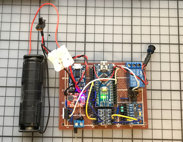
You’ll find the Deluxe Descent is fairly straightforward: an Arduino that reads an accelerometer, and can engage both a relay and a servo when a set of certain conditions are met.
Using a TP4056 battery IC with over-discharge protection, we output ~3.7V to a small step-up converter, which in turn outputs 5.2V. There’s a small loss, I expect around 10-15%. The maximum input voltage to the Arduino Nano (atmega328p) 5V pin is 5.5V, so this is safe, but we want an even 5V flowing from here. Note that the TP4056 module with DW01A has two sets of output terminals (+/-OUT and BAT+/-), one going to the battery and one going to the step-up converter. This provides low-voltage cut-off at around 2.5V on the battery to prevent damage. You should place a sliding switch (SPST type) between the TP4056 and the step-up converter, and give it some length of wire, so you can attach it to your project box. Wire OUT+ to pin 1 of a switch, and pin 2 to IN+ on the step-up module.
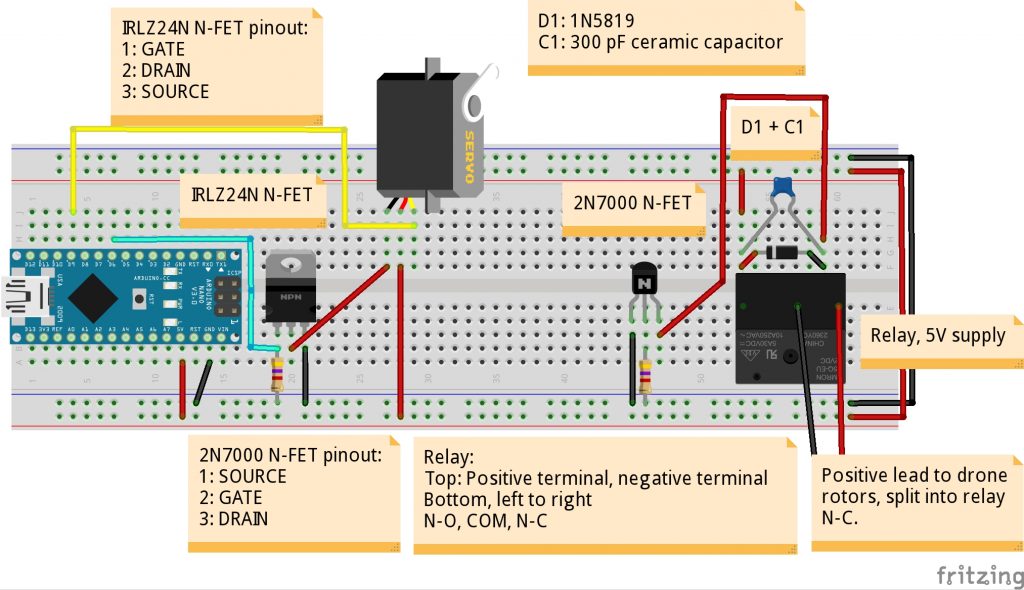
Both battery and step-up modules support ~1A, which is plenty for a relay at ~70mA, a small servo at 100-250mA, and the Arduino itself, which draws 35-40mA. Be careful to add a 1N5819 schottky diode in forward bias between the step-up converter OUT+ pin and the 5V rail you use; this protects against backfeeding if you accidentally connect your USB cable to the Arduino while it’s still connected to the rest of the circuit. Be careful not to do this, as such an error can result in anything from no harm done to a temporarily disabled USB port to all USB ports destroyed. To flash the Arduino while it’s connected to the live circuit, use a USB-TTL (TX to Arduino RX, RX to Arduino TX, GND to Arduino GND, 5V not connected), and press “Reset” just before uploading new firmware. Keep the 5V rail central, and wire it to Arduino 5V and other things (see the diagrams) and similarly find a single central place on the board to use for GND connections.


If for some reason you find your Arduino not correctly initializing hardware – intermittently, and not because of incorrect connections – it’s convenient to ask the board to reset itself. Using a small TO-92 package N-FET like the 2N7000 makes it easy. Its pinout is Source-Gate-Drain, and you only need to connect Source to Arduino GND, Gate to Arduino D8 + across a 4700-ohm pull-down resistor to Arduino GND, and finally Drain to Arduino RST pin.

If you’re an experienced drone operator, you know that a drone that doesn’t land correctly, and with its rotors still spinning, is a runaway blender. It’ll cut and chop, damaging itself, people, and property. While the killswitch is far from mandatory, it’s useful. Cut the positive lead going to the rotors (possibly four or more leads, but that’s irrelevant), and connect it to COM (short for COMMON GROUND) on the relay. Then, connect N-C (Normal-Closed) to the rotor power line again. The N-C path in the relay is always closed, i.e. conducting, except when 5V is applied to the relay, which switches it to conduct along the N-O (Normal-Open) path. This cut-off ensures that rotors have some time to spin down and deliver only a small kinetic effect to any objects they touch, even with a fully deployed parachute and DELUXE DESCENT. Connect the Arduino 5V pin to the positive terminal on the relay. You decide which is positive yourself, and whichever you decide, its opposite is the negative one. In the diagram, it’s the left terminal. Connect the negative terminal to the drain of a 2N7000 N-FET, and connect the source of the 2N7000 to GND. On the gate of the 2N7000, connect D7, but also wire a 4700-ohm pull-down resistor to ground.
You may be puzzled by the 300pF ceramic capacitor that sits in parallel with a 1N5819 schottky diode, across the terminals of the relay (the killswitch). Why is it there? It helps subdue smaller spikes resulting from energizing the relay coil, so we don’t suddenly have an Arduino that gets temperamental and intermittently resets. The diode catches the rise in voltage from the collapsing magnetic field of the relay coil, but before it can catch the rising spike, the capacitor is in place to subjugate it.
The servo is also shown in the diagram below. For a portable build, every mAh counts, so we use a MOSFET to engage/disengage power when relevant. My SG90 test servo drew ~10mA of current when idle, but this will vary with different servos. The servoPwrPin in the code controls the MOSFET, and servoPin refers to the PWM signal pin (it must be one of 3, 5, 6, 9, 10, or 11). The IRLZ24N is beefy enough to handle every 5V servo imaginable, and will likely never need a heatsink.
Read the comments, and look at the example programs for the included ADXL345 library. You should probably start with modifying freeFallThreshold, freeFallDuration, and doing drop-tests. A drop-test involves a breadboard, a battery, some components, and lots of electrical tape and bubble-wrap. If you make sure the wires are stuck in the breadboard snugly, you can drop-test from 5 meters and no harm will come to your hardware.
You can monitor the readings on the X, Y, and Z axes at any time. Simply connect with your USB cable in the Arduino IDE, and use the Serial Monitor (Ctrl+Shift+M) to send a single character to your Arduino. It’ll reply with this data and a few useful bits such as the amount of free SRAM in bytes. This is particularly helpful when calibrating your build. However, the USB cable will force a reset when connecting; if you use a USB-TTL cable, connect only the RX pin to Arduino TX, and the TX pin to Arduino RX, and GND to Arduino GND. After a drop-test, you can recover the last X, Y, Z axes readings of your running DELUXE DESCENT, and know what the accelerometer was seeing before it deployed anti-gravity countermeasures. Remember to connect a 5mm LED to Arduino D13 in series with a 220-ohm resistor to GND, and use flipLED() or just digitalWrite (13, HIGH/LOW) to blink at certain parts in the code; you can’t always have a serial connection available for debugging.
The FREE-FALL block in the loop() function is the next step when you wish to adjust what’s done in a free-fall situation. Here, you can flip levers and turn knobs to your heart’s content. There’s room for much more expansion on the Deluxe Descent – a data-logging functionality with altitude and acceleration to microSD card, and of course GPS – all this would be very nice. The Arduino Nano itself isn’t beefy enough to become a complete flight-controller, but the Raspberry Pi Zero is.
Keep your drone safe!
 Building DIY Drone from Scratch Part 3: Making GPS Follow-Me Drone
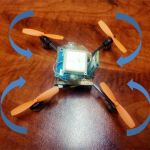 How to Build a DIY Drone from Scratch Part 2: Using Arduino Nano as a Flight Controller
 How to Build a DIY Drone from Scratch Part 1: Building a Cheap DIY Drone
 DIY Raspberry Pi Drone: Mechanics – Part 1
 ORIZURU, the Origami Crane Drone
 DIY Raspberry Pi Drone Part 2 – Naza-M Lite Guide


