![]()
 How to make your own robot on 2 wheels, using stepper motors with Arduino parts and sensors … Part 2
In Part 1, we got as far as driving a stepper motor using a library. This time, we will study the stepper motor programming in a little more detail and learn how to control it, the problems that are encountered in handling stepper motors, and some solutions.
Electronic Construction Recipe
Approximate time: 90m
Required parts
Stepper motor review
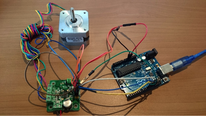
Picture 1 – Stepper motor and L6470
I will review how to control a stepper motor through programming in this post. You can see from the below characteristics that what is unique for the stepper motor compared to regular motors and servo motors is the ability to control rotation.
Also, you send PWM signals to the motor in order when actually controlling it. That said, control is difficult if you connect the Arduino directly to the stepper motor. So normally, for micro-controllers like an Arduino, you will want to control the stepper motor via a motor driver, which makes various types of control possible. (Refer to #12 for handling normal motor drivers.)
The L6470 stepper motor driver used this time is both cheap and has onboard control/oscillator circuits for detecting overcurrent to the stepper motor, DSP, and communication I/F. Fundamentally, when you’re trying to control the number of revolutions or power to the motor or accurate movement is desired, you need to choose a motor driver with functions and abilities like the one below to complete your circuit.
Because I want one that’s easy to use and cheap for this project, I’m using the L6470. But, last time and the time before that, when I tried to drive the stepper motor, I expected it to rotate. Instead, I only got noise and vibration but no turning of the axis. I wonder if I did something to make it act weird?
The phenomenon of stepper motor “step-out”
When working with stepper motors, you often encounter step-out. Put simply, step-out is what happens when a stepper motor’s actual movement doesn’t keep up with the rotation control signal and the rotational position expected by the motor driver and the actual stepper motor position get misaligned, causing a loss of synchronicity and the motor to not turn.
There are various causes of step-out. Driving the stepper motor as described below commonly causes it.
In general, when step-out occurs, the above causes are all possible but sudden acceleration or overspeed caused by insufficient torque is the most common causes. So, if your stepper motor steps out, these causes are worth investigating.
Also, STMicroelectronics sells L6470 and has a detailed description, so you can also refer to that.
Programming the stepper motor
Now, let’s dig into the subject of this post, stepper motor programming. In order to control the stepper motor from the Arduino via the L6470, you have to program the l6470 to send control signals. The circuit is as below.

Illustration 1 – A circuit connecting the Arduino, the L6470, and the stepper motor
Flow of the stepper motor control program
Below is the stepper motor program. We will now peruse the flow of this program.
|
1 2 3 4 5 6 7 8 9 10 11 12 13 14 15 16 17 18 19 20 21 22 23 24 25 26 27 28 29 30 31 32 33 34 35 36 37 38 39 40 41 42 43 44 45 46 47 48 49 50 51 52 53 54 55 56 57 58 59 60 61 62 63 64 65 66 67 68 69 70 71 72 73 74 75 76 77 78 79 80 81 82 83 84 85 86 87 |
#include <Arduino.h> #include <SPI.h> //(1) Import for SPI transmission //(2) Define the stepper motor pin #define PIN_SPI_MOSI 11 #define PIN_SPI_MISO 12 #define PIN_SPI_SCK 13 #define PIN_SPI_SS 10 void setup() { delay(1000); Serial.begin(9600); //(3) Initialize the stepper motor pin pinMode(PIN_SPI_MOSI, OUTPUT); pinMode(PIN_SPI_MISO, INPUT); pinMode(PIN_SPI_SCK, OUTPUT); pinMode(PIN_SPI_SS, OUTPUT); digitalWrite(PIN_SPI_SS, HIGH); //(4) SPI signal to commence SPI transmission SPI.begin(); SPI.setDataMode(SPI_MODE3);// When SCK is high, send/receive data, when idle, set pin to HIGH SPI.setBitOrder(MSBFIRST);// Transmission from MSB //(5) L6470 settings L6470_setup(); } //********************************************** //(6) SPI transmission method //********************************************** void L6470_send(unsigned char value){ digitalWrite(PIN_SPI_SS, LOW); SPI.transfer(value); // Send control signal via SPI transmission digitalWrite(PIN_SPI_SS, HIGH); } //********************************************** // (7) L6470 setup //********************************************** void L6470_setup(){ // Device settings L6470_send(0x00); L6470_send(0x00); L6470_send(0x00); L6470_send(0x00); L6470_send(0xc0); //Set maximum revolution speed L6470_send(0x07);//register address L6470_send(0x20);//value(10bit),default 0x41 //Voltage setting when motor is idle L6470_send(0x09);//register address L6470_send(0xFF);//value(8bit),default 0x29 //Voltage setting when motor rotating at constant speed L6470_send(0x0a);//register address L6470_send(0xFF);//value(8bit),default 0x29 //Voltage setting when accelerating L6470_send(0x0b);//register address L6470_send(0xFF);//value(8bit),default 0x29 //Voltage setting when decelerating L6470_send(0x0c);//register address L6470_send(0xFF);//value(8bit),default 0x29 //full step, half step,1/4,1/8,…,1/128 step setting L6470_send(0x16);//register address L6470_send(0x00);//value(8bit } //********************************************** // (8)Main process - loop() //********************************************** void loop(){ //360 degrees - Turn one complete revolution L6470_send(0x50);// Run(DIR,SPD),0x51:Forward,0x50:Reverse L6470_send(0x00); L6470_send(0x20);// Rotation speed settings L6470_send(0x00); delay(1604);// Turn 1 time every 1604ms L6470_send(0xB8);// Hard stop } |
Control Signals – About SPI transmission
First, the exchange of control signals between the L6470 and the Arduino occurs over a method call SPI transmission (Serial Peripheral Interface). This SPI transmission is used to exchange signals between microcontrollers like Arduinos and IC chips.
In the “#include SPI.h” expression in the program’s second line (1), I am preparing to use SPI transmission on the Arduino. When using libraries, remember there have always been these “#include <***.h>” expressions.
Next, in (2), I set the pin used by the L6470. Here you see written MOSI and MISO. These are the basic signal lines that SPI transmission uses.
In SPI transmission, signal lines are constructed of the below 3 basic elements (4 elements when using SS signals). Each signal line has specific role of either Clock (SCK), Output Signal (MOSI: Master Out Slave In), and Input Signal (MISO: Master In Slave Out). When actually transmitting, communication is arranged so that the Arduino outputs the standard Clock signal (SCK) and then together with the L6470 transmits data back and forth using the In and Out (MISO and MOSI) connections.
In (3), the pin mode for the signal line used is set. Next, in (4), the SPI transmission mode to be used is set. The device being connected determines the mode.
Once SPI transmission preparation is complete, in (5), we finally get to use SPI transmission and begin L6470 setup. The part that actually sends the SPI transmission signal is (6) where L6470_send() function is written.
When doing the L6470 setup, set up the required elements based on the specs recorded in the datasheet and manual.
When you look at the contents of the datasheet, you will see the below table of command addresses. This time, because we’re using the 12026 motor, send the register address recorded in the table via SPI transmission to initialize the L6470.
As an example of how to use the table in programming:
|
1 2 3 |
//Highest revolution speed setting L6470_send(0x07);//register address L6470_send(0x20);//value(10bit),default0x41 |
Above is the code. If we look in the table at the “highest revolution speed” function line, the address is “0x07”, the length is “10” bits, and the initial value is “0x20” (in this 12026 mode example). By sending the values in the table via SPI transmission, you can do various settings.

Table 1 L6470 Datasheet.
Once initialization is complete, the commands to actually drive the stepper motor are found in the (8) main process. You can see the various commands recorded in the datasheet again.
In the example, a forward or reverse rotation command is sent, followed by a 20 bit rotation speed command, and then delay(1604). This sets it to turn for that period of time. If this rotation speed value is changed, it can be sped up or slowed down.
This is the flow when using Arduino to drive the stepper motor via L6470. Also, corresponding to this, by changing some of the connection methods, several stepper motors can be controlled as introduced last time.
Let’s try driving a 2-wheeled robot
Now that we understand the flow of the programming functions for stepper motors, let’s finish off the 2-wheeled robot. I completed printing the wheels and body with the 3D printer in the last post and will now mount the necessary parts on the body so you can completely make your own robot.
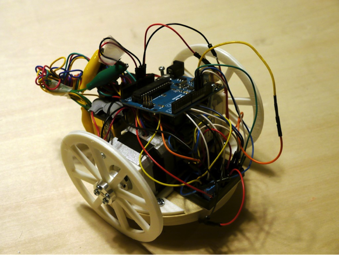
Picture 2 – All the necessary parts to make your own robot are mounted on the body
With the Arduino, breadboard, and 9V batteries for the stepper motor (2 in series) all mounted, there’s hardly any space left…Yikes.
So, rather than use an Arduino UNO, I tried changing it out for an Arduino Pro Mini.
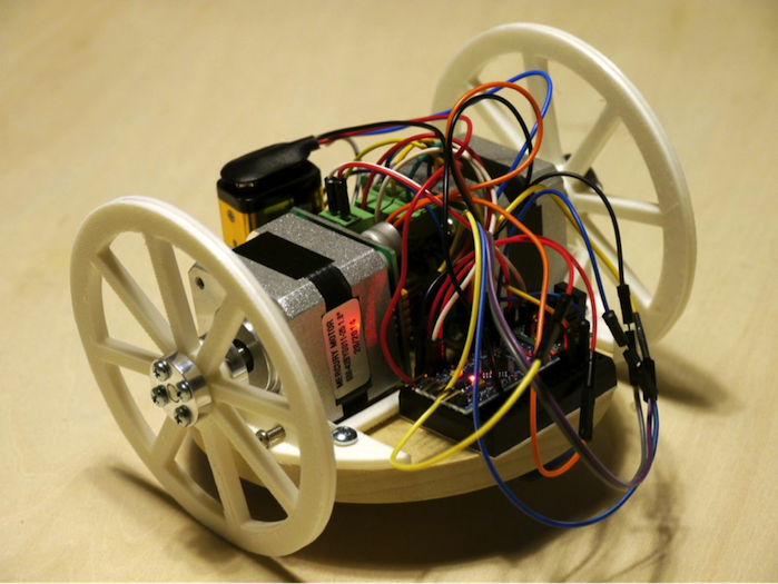
Picture 3 – With an Arduino Pro Mini, it’s perfect!
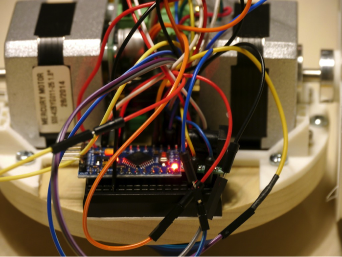
Picture 4 – It mounts neatly on the breadboard
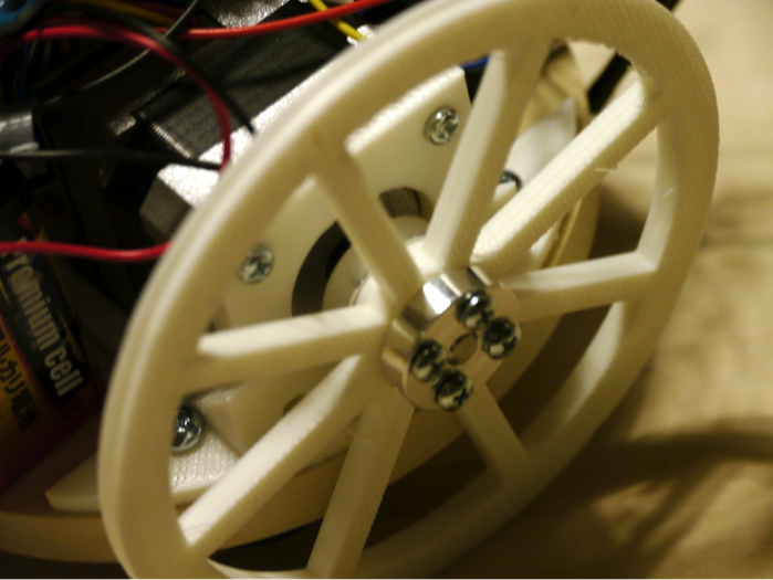
Picture 5 – Wheels mounted firmly to the axes so they don’t slip
Once all parts are mounted, we finally get to turn on the power and try driving it.
It works! In the video, a 12V adapter is attached to the stepper motors. When I connected 9V batteries they were a little too heavy and I noticed that the stepper motors didn’t have quite enough torque. In this case, if it’s too heavy, like I described earlier, you can change out the motor itself, do some weight reduction, or improve the power source a bit more to make stable operation possible.
Conclusion
This time, we used stepper motors to make your own robot on two wheels. The movement happened as written in the code. You could add other things when you make your own robot like attach light sensors on each side and make a robot that moved towards the brightest light, or a robot that moves towards sound, or even advance to a robot that could be driven by a smartphone using WIFI communication via the ESP-WROOM-02 that was introduced previously. All kinds of applications are possible. I may try to introduce some improvements in subsequent posts.
Next time, I think I will make a device that uses a magnetic sensor or something else cool.


