![]()

Once you have learned the basics of using a stepper motor you can create some fun projects, and even make your own robot. This time, I am going to try building a 2-wheeled robot using stepper motors.
In the previous post, Use Arduino to control a motor – Making an RC car using a servo motor for the steering, we made a remote control car where a normal motor provides the forward/backward movement and a servomotor controlled the steering.
In this 2-wheeled robot, the forward/backward movement and turning can be accomplished with two motors placed side by side. You often see robots that use this 2-wheel base as a source of locomotion. I’m going to make something with that kind of versatility.
Make your own robot with this electronic construction recipe
Approximate time: 90 minutes
Required parts
The design for the 2-wheeled robot

Illustration 1 – Modeling a 2-wheeled robot
To start with, you need to think about the complete design for the 2-wheeled robot. A 2-wheeled robot can be made with a simple design if it has 2 motors. 2 motors turning in the same direction gives a forward/backward motion and turning in opposite directions provides turning capability. This point, that basic motion control can be achieved very easily using two motors, is employed in many areas. Let’s measure the size of the stepper motors and other parts to be used and make a body that matches that size.
The parts for the 3D printer I used can be found here.
Illustration 1 uses the free modeling software “123d design” and shows what I was thinking for a simple design for the 2 wheeled robot’s body. I’m thinking of using a round piece of wood as a base and attaching the stepper motors, the Arduino, and the battery to it. Because a 2-wheeled robot could end up toppling over forward or backward, I will attach a small ball caster to the back of the board for support.
To determine the size of the wheels, place the stepper motor on the round piece of wood shown in Picture 1 and measure the height from the floor. To that height, add the height when the caster floats a little bit + 2-3mm and you get the diameter of the wheel.
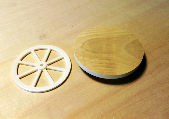
Picture 1 The round board and the wheel produced by the 3D printer

Picture 2 The support ball caster
Also, I modelled the part that locks the stepper motor to the board. The axis side of the stepper motor has four 4mm screw holes so I made a part that can use these to lock the round board to the stepper motor.

Illustration 2 The part that holds the stepper motor to the round board

Picture 3 The parts printed by the 3D printer
Once the 3D printer produced the parts, I mounted the stepper motor and confirmed the size. It fit perfectly.

Picture 4 – Parts assembly
Attach the driver to the stepper motors.
Because all of the parts are mounted on top of a 12 cm diameter board, we need to use space as cautiously as possible. Because the stepper motor driver L6470’s board and the screw hole locations and size are the same as those on the stepper motor’s surface, I can screw the driver to the back of the stepper motor. By doing so, I can save a little space.

Picture 5 – Remove the screws temporarily and attach the driver board.

Picture 6 – The driver board on the back of the stepper motor
A circuit to drive two stepper motors using Arduino
Previously, we only drove one stepper motor. This time, we need to drive two stepper motors. Using a method called daisy chaining, the L6470 can control several stepper motors.
A daisy chain is a wiring scheme in which multiple devices are wired together in sequence or in a ring. Other than a full, single loop, systems that contain internal loops cannot be called daisy chains.
The circuits needed to daisy chain with L6470 are shown below. Because there are many wires, please be careful not to make any mistakes when wiring it up.

Illustration 3 – Circuit connecting two stepper motors
The difference from when the circuit had just one is that the first and second stepper motors now have a part connecting them. After confirming with the L6470 datasheet, the first stepper motor is wired to SDO and the second stepper motor is wired to SDI. Data is sent and received through this part.
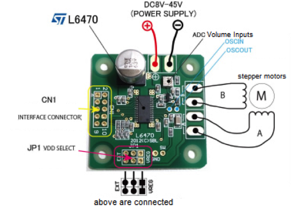
Illustration 4 – L6470 schematic diagram
Conclusion
With the circuit wiring complete, I want to say it’s time to start on the programming part but since programs dealing with multiple stepper motors can be a bit complicated, it might be wise to take a step back and learn more about stepper motor programming. If it goes well, the 2 stepper motors will sync just like in the below video.
 How To Make Your Own Robot (Part 2)
 Make a Laser Arduino Robot Using Parallax Laser Sensor – Part 1
 Make a Laser Arduino Robot Using Parallax Laser Sensor – Part 2
 An Intro to: CMUcam5 Pixy Vision Camera Sensor
 Guide to Connecting Arduino & Raspberry Pi + DIY Arduino and Raspberry Pi Camera Robot!
 Intro to CMUcam5 Pixy Vision Camera Sensor Part 2 – Creating a Ball Balance Beam


