![]()
Ever wondered how parking sensors work, how your car knows how far you are from colliding with the wall? Ever seen robots avoiding the obstructions and wondered how they detect them? The answers to said questions involve short-range distance measurement. In this project, Arduino UNO coupled with ROHM distance measurement sensors will be used to measure the distance of a wooden target within 15 cm.
Although the project seems simple, the sensors do not directly give the distance to the target. In this case, we have a phototransistor that outputs a certain voltage based on the distance to the target. That voltage has to be translated into distance. The complexity of the method aggravates due to the fact that the variation of voltage generated by the phototransistor is not in linear relation with distance. This involves a method called curve fitting to obtain the closest possible equation from the experimental data. The following lessons will be learned by this project:
How to correctly power an LED:

In this DIY project, we’ll develop a circuit to power up the LED of a distance measuring sensor using a digital pin from Arduino. The light emitted by the LED will be reflected from a wooden target and received by a phototransistor which will generate a voltage signal to be read by an analog pin in Arduino. Since the voltage changes are not linear in relation to distance changes, the collected data at different distances of the target will be used to generate a governing equation using MATLAB. Further, the equation will be used in the code to measure distance with Arduino. An explanation of this project will follow the following sequence:
Required components:
| Component | Link/Image |
| ROHM Distance measurement sensor
RPR-220PC30N |
https://www.digikey.com/products/en?keywords=RPR-220PC30N |
| Note that I used RPR-220UC30N which emits red light in this article, but linked to an alternative parts, RPR-220PC30N, which is currently easier to find & purchase. This one emits blue light, but the function is the same. | 
|
| Arduino UNO R3 | https://www.aliexpress.com/item/32981776049.html
|
| USB B Cable (Mostly Comes in package with Arduino UNO R3) |

|
| 56kOhm and 220 Ohm Resistors | 
|
| 400 Point Solderless Breadboard | https://www.aliexpress.com/item/32711841420.html 
|
| 10 x Jumper wires | https://www.aliexpress.com/item/32951945552.html 
|
Once all the components have been procured, the first step is connecting everything. This project does not require many components; only Arduino is required to be wired correctly with a ROHM RPR-220 sensor with correct resistors. Practically, in order to make it a portable system, we have used double-sided tape to attach Arduino on the back side of the breadboard and a ROHM sensor on the front side of the breadboard. The terminals of the ROHM sensor are defined here:

Connection schematics are shown here:

The actual wiring will appear as such:


Programming of Arduino requires setting up Arduino IDE. Arduino IDE is available for Linux and Windows. For this DIY project, we will be using a Windows desktop application. Visit the following link to download and install Arduino IDE:
After a successful installation, open Arduino IDE and connect your Arduino UNO R3 using USB B Cable. Select the appropriate COM Port from Tools > Port > COM 3 (Arduino Genuino / UNO) in Arduino IDE. At this stage, your setup is complete, and you may begin the programming.
Initially, the program will be developed to obtain the sensor values when the target is placed at different distances. The commented code is here:
|
1 2 3 4 5 6 7 8 9 10 11 12 13 14 15 16 17 18 19 20 21 22 23 24 |
#define IR_INPUT_PIN A0 //Pin to read values from phototransistor #define IR_LED_PIN 8 //Pin to light LED void setup() { Serial.begin(9600); pinMode(IR_INPUT_PIN, INPUT); pinMode(IR_LED_PIN, OUTPUT); } void loop(){ int ambient = 0; int lit = 0; int value = 0; digitalWrite(IR_LED_PIN, LOW); //Turning off LED to measure ambient light delay(5); //To give ADC and LED transition time ambient = analogRead(IR_INPUT_PIN); //Saving value for ambient light digitalWrite(IR_LED_PIN, HIGH); //Turning on LED delay(5); lit = analogRead(IR_INPUT_PIN); //Measuring total reflected light on sensor value = lit - ambient; //Removing ambient light value to calculate the net value of LED Serial.print("value = "); Serial.println(value); //Printing final sensor value on serial monitor delay(1000); } |
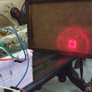
Once the above mentioned code is completed, compile and upload it to Arduino. If all the wiring is correct, the LED will light up. Setup apparatus for calibration are shown below (place a target at a 15 cm distance with scale placed underneath):

Now in Arduino IDE, open Tools > Serial monitor. Proceed as follows:
Above mentioned, values may differ depending upon the color of the target, ambient light and environment. In my case, values were 15, 30, 97 and 487 against 15, 10, 5 and 2c, respectively.

It is evident that the relationship is not linear and we need an equation for the code to measure distance. That equation will be obtained using the curve fitting method explained in the next section.
Open MATLAB, write x and y coordinates data as shown:

Now go to curve fitting in apps.

Choose type of fit as power.

Note the equation and values of constants a and b.
In the final programming, the code will be modified to include the equation obtained from curve fitting and print commands will be removed except the final distance, which is required. Since the relation between sensor values and distance has been found using curve fitting, an additional variable will be declared to store the magnitude of distance.
|
1 2 3 4 5 6 7 8 9 10 11 12 13 14 15 16 17 18 19 20 21 22 23 24 25 26 27 28 29 30 31 32 33 |
#define IR_INPUT_PIN A0 //Pin to read values from phototransistor #define IR_LED_PIN 8 //Pin to light LED double a= 73.11; //Constants obtained from MATLAB Curve fitting double b= -0.585; double dist; void setup() { Serial.begin(9600); pinMode(IR_INPUT_PIN, INPUT); pinMode(IR_LED_PIN, OUTPUT); } void loop() { int ambient = 0; int lit = 0; int value = 0; digitalWrite(IR_LED_PIN, LOW); //Turning off LED to measure ambient light delay(5); //To give ADC and LED transition time ambient = analogRead(IR_INPUT_PIN); //Saving value for ambient light digitalWrite(IR_LED_PIN, HIGH); //Turning on LED delay(5); lit = analogRead(IR_INPUT_PIN); //Measuring total reflected light on sensor value = lit - ambient; //Removing ambient light value to calculate the net value of LED //Using power function and formulating equation generated by MATLAB dist = pow(value,b); dist = a*dist; //Displaying the calculated distance Serial.print(dist); Serial.println(“ cm”); } |
In testing, use the same setup for calibration.
After uploading the final code to your Arduino, open the serial monitor. You will see the values of distance in centimeters. In order to validate the test, match the values on-screen with a ruler on the ground. If the values are nearly correct, you have successfully applied the curve fitting method for approximation. Now your system is reliable to find the distance to similar obstructions in different scenarios.
 Make a Stevenson Screen with Arduino Part 4 – Project Completion with Case Building and Soldering
 How To MacGyver A Laser Tripwire Using Arduino
 Make a Laser Arduino Robot Using Parallax Laser Sensor – Part 1
 How to Use Map Function Using Arduino
 How to connect your Arduino to Wi-Fi
 SALTO the Agile Jumping Robot