![]()
Sometimes you really need to know what’s going on inside your device, sometimes you want to use more than one device, or maybe you want to add some external modules to your device. In all these cases, you need to use Serial communication. Today we are going to build a very simple system where you push a button that sends a message to the computer asking if the light should be ON or OFF, and turn an LED on and off based on the answer.
Today’s recipe
The code for today is available on github.
What is serial communication?
Serial communication is the most commonly used method to send information between two devices in the simplest way: sending it bit by bit. Essentially the information is passed back and forth by setting a pin high or low with a predefined frequency, called baud rate. The Arduino UNO board comes with a predefined serial port with two pins. These two pins are available on digital pin 0 (RX) and 1 (TX), but it is important to keep in mind: The USB port is also using the same two pins, so if you want to use the Serial Monitor, keep these two pins unconnected. Additionally, if you need it, you can also set up extra serial channels with the SoftwareSerial library.
Setting up our system

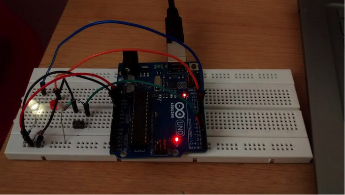
Figure 1: Prototype setup

Figure 2: Connection diagram
Our simple example of the Arduino serial communication system will consist of a push button and two LEDs: one to indicate if the system is working, and one that we are going to control through the Serial Monitor. Both LEDs are connected to a 5V digital output pin and they are also serially connected to a 220 Ohm resistor. This allows us to limit the amount of current flowing across the LEDs.
Connecting the button circuit
We are going to use a very simple push button on the digital pin 2 for this project. By default the button circuit is open which indicates that the input pin is high. When the button is pushed, the input pin connects to the ground (LOW).

Figure 3: Button circuit
Arduino code
Now, let’s write some code. First, we need to define our pins that we will be using and write the setup function. In the setup function, first initialize the pins and open the serial communication. Upload and run the following codes on your Arduino.
|
1 2 3 4 5 6 7 8 9 10 11 12 13 14 15 16 17 18 19 |
//input button int btn=2; //LED that indicates the state of our system: Slowly blinking when waiting for the button, permanently ON when communicating int blinkingled=9; //this is the LED that we are going to toggle from the computer int mainled=8;void setup() { //defining pin modes pinMode(btn, INPUT); pinMode(blinkingled, OUTPUT); pinMode(mainled, OUTPUT); //attaching an interrupt to the input pin: the btn_ISR function will be called each time when the button is LOW attachInterrupt(digitalPinToInterrupt(btn), btn_ISR, LOW); //defining default values for the outputs digitalWrite(blinkingled, LOW); digitalWrite(mainled, LOW);// starting serial communication with the baud rate 9600 bits/second Serial.begin(9600); Serial.println("hello!"); } void loop() {} void btn_ISR(){} |
Once your Arduino serial communication code is uploaded, open the Serial Monitor by going to Tools, Serial Monitor. Set the baud rate to 9600, then choose Both NL & CR option on the bottom right corner. If you did everything correctly, you should see a welcome message like this:

Figure 4: Serial Monitor
Adding a button interrupt
In the setup function, you can see the following line:
attachInterrupt(digitalPinToInterrupt(btn), btn_ISR, LOW);
So, what does it really do? Well, basically this command line prevents further execution on Arduino and calls the btn_ISR function each time the btn pin is LOW (each time you press the button). Keep in mind that on an Arduino Uno interrupts can only be attached to Pin 2 and 3.
Writing the loop function
We have now reached the most important part of our code: the loop function. Arduino needs to run the following three things repeatedly in a given order:
With a global variable (systemstate), we can indicate whichever state we are in. When the systemstate is 0, your Arduino waits for an interrupt to happen (the red LED blinks slowly). When the systemstate is 1, your Arduino sends out the question and then automatically changes to state 2, where it stays until there is an answer available on the serial line. When the answer arrives, we read it to a local string, and compare it to our two expected answers: “onrn” or “offrn”.
So, why do we have this “rn“ at the end of the expected strings? When we chose Both NL & CR in the Serial Monitor, we instructed the computer to automatically add a “r” (carriage return) and a “n” (new line) characters to the end of our message. Therefore, when you type in “on”, your Arduino is going to receive the message as “onrn”.
Now, you just need to upload the full code below, open the Serial Monitor and you can start talking to your Arduino.

Figure 5: Arduino blinking red light

Figure 6: Serial Monitor with 9600 baud rate and Both NL & CR option
The full code:
|
1 2 3 4 5 6 7 8 9 10 11 12 13 14 15 16 17 18 19 20 21 22 23 24 25 26 27 28 29 30 31 32 33 34 35 36 37 38 39 40 41 42 43 44 45 46 47 48 49 50 51 52 53 54 55 56 57 58 |
<p style="background-color: grey;">//input button int btn = 2; //LED that indicates the state of our system: Slowly blinking when waiting for the button, permanently ON when communicating int blinkingled = 9; //this is the LED that we are going to toggle from the computer int mainled = 8; //a variable to define the current state of the system int systemstate = 0; void setup() { //defining pin modes pinMode(btn, INPUT); pinMode(blinkingled, OUTPUT); pinMode(mainled, OUTPUT); //attaching an interrupt to the input pin: the btn_ISR function will be called each time when the button is LOW attachInterrupt(digitalPinToInterrupt(btn), btn_ISR, LOW); //defining default values for the outputs digitalWrite(blinkingled, LOW); digitalWrite(mainled, LOW); // starting serial communication with the baud rate 9600 bits/second Serial.begin(9600); Serial.println("hello!"); } void loop() { //waiting for the button to be pushed: slow blinking if (systemstate == 0) { digitalWrite(blinkingled, HIGH); delay(500); digitalWrite(blinkingled, LOW); delay(500); } //sending out the message on the Serial line if (systemstate == 1) { digitalWrite(blinkingled, HIGH); Serial.println("ON or OFF?"); systemstate = 2; } //receiving the answer if (systemstate == 2) { //waiting until the answer is available while (!Serial.available()) {}; //reading the answer to a string String a= Serial.readString(); if (a=="offrn") { digitalWrite(mainled, LOW); }; if (a=="onrn") { digitalWrite(mainled, HIGH); }; //restarting again systemstate = 0; } } void btn_ISR() { //only reacts if the system is in state 0 if (systemstate == 0) { systemstate = 1; } }</p> |


