![]()

Imagine you’ve just moved into a new place. You need furniture ASAP but you don’t have measure tape with you. Well, this Parallax laser Arduino robot would come in very handy!
In the previous posts, How To Make Your Own Robot and How To Make Your Own Robot (Part 2), we showed a simple way to build your own robot from scratch using Arduino UNO R3. In this article, we will further improve the functionality of the robot by making it mobile and adding laser range finder (LRF) to allow the robot to detect objects and measure distances.
The laser sensor will allow us to obtain more accurate and reliable data. This Arduino robot is designed to be autonomous. It’ll be able to detect and avoid obstacles as they roam around.
The robot is designed to:
The sensor is attached to a servo so the robot can pan left and right to take several measurements. The distance measured is then displayed on a small OLED. We’ll use stepper motor for smooth, quiet operation.
We will discuss the building of this Arduino robot step by step, first step is the basic installation of the chassis, motors and Arduino/motor shield. Then a small program was shown to test the motors to ensure proper connections and software installation. Then, in the next article we will add on the rest of the devices one by one, followed by programs to test correct installation and connection. By doing this approach, if any problem occurs, it will be easier to fix.
The hardware required for this robot are available in many electronics shops, we provide examples of shops in the Hardware list.
Install motors, wheels, and the acrylic base
The chassis from Parallax is made from strong aluminium. It is specifically designed for servo instead of stepper motor, so we need to make a little modification to the design.
First, we will cut the lower part of both sides of the chassis to save space for motor attachment. Use Dremel to get a clean cut.
We’re using NEMA 17 stepper motor, which has a resolution of 200 steps/revolution. It can be powered at 12V 350mA.
To install motors we need 6.5 cm x 4.5 cm acrylics for mounting motor into the chassis as shown in Figure 1. Cut the acrylics using hacksaw and drill the holes by using Dremel. Use M2 x 10mm screws to attach motors into the acrylics mounting; it requires 8 screws for both motors. Then, attach the acrylics into the chassis.

Figure 1. Mounting stepper motor to 6.5 x 4.5 cm acrylic board
Cut 15 cm x 8 cm acrylics for the base to attach Arduino and OLED display (Figure 2). Install the acrylics base using 4 spacers and screws, then install tail wheel using the pin provided.

Figure 2 Chassis, tail wheel and 15 x 8 acrylic board for the base

Figure 3. Wheels and shaft connectors

Figure 4. Stepper motors and tail wheel attached to the chassis
To install the wheels, we use shaft connectors as shown in Figure 3. There is one small modification required. The diameter of the hole of the shaft is 4mm, whereas the stepper motor’s shaft has diameter of 5mm. So we need to make the connector’s hole bigger to 5 mm. Use round file or Dremel to make the hole bigger. Do it carefully.

Figure 5. Acrylic base installed to chassis
Pull the cables from motors through the holes provided to the top, and put the battery under the chassis using double tapes. Lipo (Lithium Polymer) battery is the perfect solution for this project as it gives 11.1V 800mAh~1000mAh, which allowswill runtime for more than 1 hour. It’s also rechargeable. But we need a special charger for this battery. If you are an aeromodeller or RC car driver then you must be familiar with this type of battery. It can be replaced with 6 or 8 x AA batteries that provide 9-12 V.

Figure 6. Attach battery to chassis using double tape
Connect cable from motors to motor shield
Adafruit motor shield specs – Adafruit
This motor shield is capable of running 2 stepper motors and 2 servos. The beauty of this stepper motor shield is that it does not use any pin in Arduino because it is connected through I2C. The only pin needed is for servo. Just follow the instruction to connect the wires from motors.
To learn the basics of stepper motor and its connection to Arduino UNO R3, please refer back to Using Arduino with Parts and Sensors – Stepper Motor Part 1
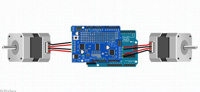
Figure 7. Connecting stepper motors to motor shield

Figure 8. Arduino and motor shield attached to acrylic base
Now simply install the wheels and battery connector as shown below.

Figure 9. Stepper motor’s cable connected to motor shield
Install Software and upload the code
We are now ready to run our first code. First, we need to install Arduino IDE from Arduino website and motor shield library from Adafruit. After successful installation, copy the following source code to the Arduino.
|
1 2 3 4 5 6 7 8 9 10 11 12 13 14 15 16 17 18 19 20 21 22 23 24 25 26 27 28 29 30 31 32 33 34 35 36 37 38 39 40 41 42 43 44 45 46 47 48 49 50 51 52 53 54 55 56 57 58 59 60 61 62 63 64 65 66 67 68 69 70 71 72 73 74 75 76 77 78 79 80 81 82 83 84 85 86 87 88 89 |
//******************************************************************************************************************************************* #include <Wire.h> #include <Adafruit_MotorShield.h> #include "utility/Adafruit_MS_PWMServoDriver.h" Adafruit_MotorShield AFMS = Adafruit_MotorShield(); Adafruit_StepperMotor *myMotor1 = AFMS.getStepper(200, 1); Adafruit_StepperMotor *myMotor2 = AFMS.getStepper(200, 2); void setup() { Serial.begin(9600); // set up Serial library at 9600 bps Serial.println("Stepper test!"); AFMS.begin(); // create with the default frequency 1.6KHz myMotor1->setSpeed(100); // 100 rpm myMotor2->setSpeed(100); // 100 rpm } void loop() { Motor(50,3); // turn Left for 50 steps delay(1000); Motor(100,4); // turn Right for 100 steps delay(1000); Motor(50,3); // turn Left for 50 steps (back to original position) delay(1000); Motor(400,1); // move Forward for 400 steps delay(1000); Motor(400,2); // move Backward for 400 steps delay(1000); } //******************************************* ************************************* void Motor(int x,int y) { int i = 0; for ( i; (i < x); i ++) { if (y == 1) // move forward { myMotor1->step(1, FORWARD, SINGLE); myMotor2->step(1, BACKWARD, SINGLE);} if (y == 2) // move backward {myMotor1->step(1, BACKWARD, SINGLE); myMotor2->step(1, FORWARD, SINGLE);} if (y == 3) // move left { myMotor1->step(1, FORWARD, SINGLE); myMotor2->step(1, FORWARD, SINGLE);} if (y == 4) // move right { myMotor1->step(1, BACKWARD, SINGLE); myMotor2->step(1, BACKWARD, SINGLE);}} } //******************************************************************************************************************************************** |
This code is very simple. It allows the robot to make 90 degree turns to the left and 90 degree turns to the right. It also allows turning back to original position, moving forward for 400 steps and moving backward to the original position. Within the loop we run Motor function, which has 2 parameters. The first parameter tells how many steps the motor must turn and the second parameter tells about the direction (e.g. forward, backward, left and right).
When the program is running, the Arduino robot will move like in the above video.
In the next article, we will continue adding the rest of the parts such as the servo and Laser Range Finder (LRF) and writing a program that allows the robot to move around autonomously. So stay tuned for my next article!


