![]()
Originally published by Nov 10, 2016
Click here to read Part 1 of this article >
In the previous article Make Your Own Arduino RFID Door Lock, we made an Arduino RFID door lock. We were able to unlock a door using a RFID tag or a keypad. Well, what if you want to simplify the process even more? In this second part, we will add an extra feature: unlocking the door using your smartphone. It is an easier way to control the door, especially when everyone prefers having a single device that can give you access to everything. So how can we do this? We’ll connect a Bluetooth module to the previous set-up and also connect the electrical door.
In this step we will take close look at the HC-05 Bluetooth module.
Arduino-info Wiki
There are two modes of operation:
For our application, we will use the DATA Mode because we only need to use the serial communication to receive information from our mobile phone.
For more information about serial communication, please refer back to Arduino Serial Communication Tutorial.

Figure 1: The pins of the Bluetooth module
In this application we need to use the following pins-Arduino-info Wiki:

Figure 2: Wire diagram of HC-05 and Arduino Nano

Figure 3: Connection between Bluetooth and Arduino
The Bluetooth uses the serial communication; “Serial.write(Serial.read());” command will work without any problem with the RX and TX pins connected. In case of the Bluetooth module where this rule doesn’t apply, the code below will return the same texts that you write in Arduino IDE.
|
1 2 3 4 5 6 7 8 9 10 11 |
void setup(){ Serial.begin(9600); Serial.println("What did you say?:"); } void loop(){ if (Serial.available()) Serial.write(Serial.read()); } |
You need to find the Arduino programming port in Device Manager; after you connect the Bluetooth the “Standard serial over Bluetooth link” will appear and you must select “USB-SERIAL” in order to program the Arduino. You need to use a serial cable to upload your program. You cannot use Bluetooth wireless to upload programs to the board.

With RX and TX connected you will receive lots of errors like shown below:

In order to avoid these errors, you need to upload the program WITHOUT the Bluetooth TX pin connected to the Arduino Board. The TX pin of the Bluetooth has a LOW impedance and the RX input of the Arduino has a HIGH impedance. The resulting impedance will be a LOW one and the RX input will be bypassed (the current generated from the USB port is directed through the Bluetooth’s output, instead of the Arduino Board). This is the reason why the data will not be transmitted to its desired destination. In addition, pushing a current into an output of a device will create a wrong connection between the modules, and this will lead to an electrical error. What we’re trying to do is to program the Arduino, not to send data to the Bluetooth module.
After you disconnect the TX pin of the Bluetooth, everything will work fine and you can upload the code.

Figure 4: Electrical error that occurs when the pin TX of Bluetooth is connected

Figure 5: Wire diagram of HC-05 and Arduino Nano showing correct connection before uploading the code
After the code is uploaded, the next step will be to connect to the Bluetooth on your computer. You need to reconnect the TX pin of the Bluetooth because now we will use wireless communication and the serial cable is only used for power.
Follow the following steps to connect the Bluetooth to PC (on Windows 10):

Figure 6: Connecting the Bluetooth module on Windows 10
If you’ve followed the steps above, your Bluetooth connection should work and you can test your module. Here is a simple way to check if the connection has been successfully established: Type a word in Arduino IDE and see if it returns the same word. If it does, then you’re good to go! If not, then go back and try to re-pair the bluetooth.
Because we are no longer using the serial communication through cable, we need to find the COM of the Bluetooth. We need to go back to Device Manager at the PORTS section and search for the Bluetooth device. In my case it is PORT 17:

After you find the COM in Device Manager, you need to do the same (i.e. set COM port to COM 17) in Arduino IDE. You need to click on TOOLS → PORT → COM 17.

Figure 7: Setting COM in Arduino IDE
After you select the right COM, you can test your module to see if it works correctly.
Make sure you have the following two selected in the Serial Monitor:
For our demonstration, we will type in the message “Hello!”:

The output should show the same message:

Let’s refer back to the previous article Make Your Own Arduino RFID Door Lock! We’ll be using the same components as before and adding one more which is the Bluetooth module (HC-05). In order to transfer data from your smartphone to the Arduino we need the Bluetooth module.
It is important to disconnect the TX pin of the Bluetooth because otherwise we’ll get the same errors like in the first step.
There are 3 ways to unlock the door:

Figure 8: Wire diagram of all the components
The lock has a very high current consumption (800mA). Let’s add a green LED to see if the code works. The LED will be HIGH when the “*123456#” code is typed in and the system is unlocked.

Figure 9: Connections between the components
In the next step, we’ll add a battery and a relay. We’ll be using two 9V batteries to power the door. If you decide to mount the device to a fixed place you need to buy a device that gives you 5V from the 220V from the switching power supply.
Because the current consumption of the lock is high, the batteries are in parallel connections. In this case, the Arduino needs to be powered from the batteries. We need to use a DC-DC Step-Down Module that converts 9V to 5V. The input voltage enters in the Vin pin of the Arduino Board. We will no longer use the supply from the USB from the computer.
The step-down module needs to be fixed on the output voltage of 5V. You need to have a multimeter for calibration; the input voltage is 9V and we will spin the potentiometer until the output voltage is 5V.

Figure 10: DC-DC step-down module (MP1584EN)

Figure 11: Measuring the batteries

Figure 12: Wire diagram of the final setup

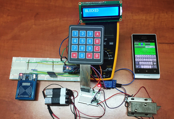
Figure 13: The final setup
|
1 2 3 4 5 6 7 8 9 10 11 12 13 14 15 16 17 18 19 20 21 22 23 24 25 26 27 28 29 30 31 32 33 34 35 36 37 38 39 40 41 42 43 44 45 46 47 48 49 50 51 52 53 54 55 56 57 58 59 60 61 62 63 64 65 66 67 68 69 70 71 72 73 74 75 76 77 78 79 80 81 82 83 84 85 86 87 88 89 90 91 92 93 94 95 96 97 98 99 100 101 102 103 104 105 106 107 108 109 110 111 112 113 114 115 116 117 118 119 120 121 122 123 124 125 126 127 128 129 130 131 132 133 134 135 136 137 138 139 140 141 142 143 144 145 146 147 148 149 150 151 152 153 154 155 156 157 158 159 160 161 162 163 164 165 166 167 168 169 170 171 172 173 174 175 176 177 178 179 180 181 182 183 184 185 186 187 188 189 190 191 192 193 194 195 196 197 198 199 200 201 202 203 204 205 206 207 208 209 210 211 212 213 214 215 216 217 218 219 220 221 222 223 224 225 226 227 228 229 230 231 232 233 234 235 236 237 238 239 240 241 242 243 244 245 246 247 248 249 250 251 252 253 254 255 256 257 258 259 260 261 262 263 264 265 266 267 268 269 270 271 272 273 274 275 276 277 278 279 280 281 282 283 284 285 286 287 288 289 290 291 292 293 294 295 296 297 298 299 300 301 302 303 304 305 306 307 308 309 310 311 312 313 314 315 316 317 318 319 320 321 322 323 324 325 326 327 328 329 330 331 332 333 334 335 336 337 338 339 |
#include <EEPROM.h> #include <SPI.h> #include <MFRC522.h> #include <Wire.h> #include <LiquidCrystal_I2C.h> #include <Keypad.h> int state_bt=1; int relPin; int stare=0; byte COD[10]; byte AUX[10]; int k=0; String codacces="*123456#"; String codpairing="*654321#"; //nfc #define RST_PIN 9 // Configurable, see typical pin layout above #define SS_PIN 10 // Configurable, see typical pin layout above MFRC522 mfrc522(SS_PIN, RST_PIN); // Create MFRC522 instance #define NEW_UID {0xDE, 0xAD, 0xBE, 0xEF} MFRC522::MIFARE_Key key; //lcd LiquidCrystal_I2C lcd(0x27,16,2); //TASTATURA const byte numRows= 4; //number of rows on the keypad const byte numCols= 4; //number of columns on the keypad //keymap defines the key pressed according to the row and columns just as appears on the keypad char keymap[numRows][numCols]= { {'1', '2', '3', 'A'}, {'4', '5', '6', 'B'}, {'7', '8', '9', 'C'}, {'*', '0', '#', 'D'} }; //Code that shows the the keypad connections to the arduino terminals byte rowPins[numRows] = {2,3,4,5}; //Rows 0 to 3 byte colPins[numCols]= {A0,7,8,9}; //Columns 0 to 3 //initializes an instance of the Keypad class Keypad myKeypad= Keypad(makeKeymap(keymap), rowPins, colPins, numRows, numCols); void setup() { pinMode(A0,OUTPUT); digitalWrite(A0,HIGH); pinMode(A3,OUTPUT); digitalWrite(A3,HIGH); pinMode(A1,OUTPUT); digitalWrite(A1,HIGH); pinMode(A2,OUTPUT); digitalWrite(A2,LOW); pinMode(6,OUTPUT); digitalWrite(6,HIGH); //nfc Serial.begin(9600); // Initialize serial communications with the PC Serial.println("What did you say?:"); while (!Serial); // Do nothing if no serial port is opened (added for Arduinos based on ATMEGA32U4) SPI.begin(); // Init SPI bus mfrc522.PCD_Init(); // Init MFRC522 card for (byte i = 0; i < 6; i++) { key.keyByte[i] = 0xFF; } lcd.init(); lcd.backlight(); lcd.setCursor(0,0); lcd.clear(); lcd.print("BLOCKED"); } void citireNFC(){ for (byte i =0; i<(mfrc522.uid.size); i++) { COD[i]=mfrc522.uid.uidByte[i]; } Serial.print("COD"); Serial.print(COD[0]); Serial.print(COD[1]); Serial.print(COD[2]); Serial.print(COD[3]); } void pairNFC(){ Serial.println("COD in pair"); Serial.print(COD[0]); Serial.print(COD[1]); Serial.print(COD[2]); Serial.print(COD[3]); long r=0; int c=0; for(int i=1;i<=EEPROM.read(0);i++) { switch(i%4) { case 1 :{AUX[0]=EEPROM.read(i); break;} case 2 :{AUX[1]=EEPROM.read(i); break;} case 3 :{AUX[2]=EEPROM.read(i); break;} case 0 :{AUX[3]=EEPROM.read(i); break;} } if((i)%4==0) { Serial.println(r); if( AUX[0]==COD[0] && AUX[1]==COD[1] && AUX[2]==COD[2] && AUX[3]==COD[3] ) { lcd.clear(); lcd.setCursor(0,0); lcd.print("CODE ALREADY IN"); lcd.setCursor(0,1); lcd.print("SYSTEM"); delay(2000); c=1; break; } } } if(c==0) { int ttt=EEPROM.read(0); Serial.println("CODE PAIRED"); Serial.print(COD[0]); Serial.print(COD[1]); Serial.print(COD[2]); Serial.print(COD[3]); EEPROM.write(ttt+1,COD[0]); EEPROM.write(ttt+2,COD[1]); EEPROM.write(ttt+3,COD[2]); EEPROM.write(ttt+4,COD[3]); ttt=ttt+4; Serial.println("ttt"); Serial.println(ttt); EEPROM.write(0,0); EEPROM.write(0,ttt); lcd.clear(); lcd.setCursor(0,0); lcd.print("CODE PAIRED"); delay(2000); } } boolean validareNFC(){ boolean c=false; for(int i=1;i<=EEPROM.read(0);i++) { switch(i%4) { case 1 :{AUX[0]=EEPROM.read(i); break;} case 2 :{AUX[1]=EEPROM.read(i); break;} case 3 :{AUX[2]=EEPROM.read(i); break;} case 0 :{AUX[3]=EEPROM.read(i); break;} } if((i)%4==0) { if( AUX[0]==COD[0] && AUX[1]==COD[1] && AUX[2]==COD[2] && AUX[3]==COD[3]) c=true; } } return c; } int comparareCOD(String a) { if(a.equals(codacces)) return 1; else if(a.equals(codpairing)) return 2; else return 0; } String iaCOD(char x) { char vec[10]; vec[0]=x; lcd.setCursor(0,0); lcd.clear(); lcd.print('X'); for(int i=1;i<8;i++) { vec[i]=myKeypad.waitForKey(); lcd.print('X');} vec[8]=NULL; String str(vec); return str; } void loop() { //Start BT autentification if(Serial.available()) { char c=Serial.read(); switch (state_bt) { case 1: if(c=='*') state_bt=2; else state_bt=1; break; case 2: if(c=='1') state_bt=3; else state_bt=1; break; case 3: if(c=='2') state_bt=4; else state_bt=1; break; case 4: if(c=='3') state_bt=5; else state_bt=1; break; case 5: if(c=='4') state_bt=6; else state_bt=1; break; case 6: if(c=='5') state_bt=7; else state_bt=1; break; case 7: if(c=='6') state_bt=8; else state_bt=1; break; case 8: if(c=='#') state_bt=9; else state_bt=1; break; case 9: lcd.init(); lcd.backlight(); lcd.print("OPEN"); digitalWrite(6,LOW); delay(5000); digitalWrite(6,HIGH); lcd.init(); lcd.backlight(); lcd.print("BLOCKED"); state_bt=1; break; default: break; } } switch(stare){ case 0: { mfrc522.PCD_Init(); if ( mfrc522.PICC_IsNewCardPresent() && mfrc522.PICC_ReadCardSerial() ) { citireNFC(); if(validareNFC()) { stare=1; lcd.clear(); lcd.setCursor(0,0); lcd.print("VALID NFC CODE"); delay(1000); return; } else { lcd.clear(); lcd.setCursor(0,0); lcd.print("INVALID NFC CODE"); delay(1000); lcd.setCursor(0,0); lcd.clear(); lcd.print("BLOCKED"); return; } } char c=myKeypad.getKey(); if(c != NO_KEY) { String codcurent=iaCOD(c); int A=comparareCOD(codcurent); if(A==0) { lcd.clear(); lcd.print("INVALID CODE"); delay(2000); lcd.setCursor(0,0); lcd.clear(); lcd.print("BLOCKED"); return;} if(A==1) { lcd.setCursor(0,0); lcd.clear(); lcd.print("VALID CODE"); delay(2000); stare = 1; return;} if(A==2) { stare=2; lcd.clear(); lcd.setCursor(0,0); lcd.print("Pairing..."); delay(2000); return;} } break; } case 1: { lcd.clear(); lcd.setCursor(0,0); lcd.print("UNLOCKED"); digitalWrite(A3,LOW); digitalWrite(A1,LOW); digitalWrite(A2,HIGH); //tone(6,3000,5010); digitalWrite(6,LOW); delay(5000); digitalWrite(6,HIGH); digitalWrite(A3,HIGH); digitalWrite(A1,HIGH); digitalWrite(A2,LOW); stare=0; lcd.setCursor(0,0); lcd.clear(); lcd.print("BLOCKED"); return; } case 2: { mfrc522.PCD_Init(); if ( mfrc522.PICC_IsNewCardPresent() && mfrc522.PICC_ReadCardSerial() ) { citireNFC(); pairNFC(); stare=0; delay(2000); lcd.clear(); lcd.setCursor(0,0); lcd.print("BLOCKED"); } break; } } } |
In this step, we will create the application for our system. I used the program MIT App Inventor 2. This is a simple program which doesn’t require a high level of programming skills. It can be downloaded from here: MIT AppInventor. In order to open this application you need to:
After you install the program, you will find a graphic interface like the following:

Figure 14 : MIT AppInventor
In order to test your application, you need to download “MIT AI2” app on your phone from Google Play. This is a free application made specifically for syncing the web apps with your smartphone.

Figure 15: MIT AppInventor on Google Play
If you want to see the screen of the app on your phone, you need to click on the Connect → AI Companion

Figure 16 : Connecting the app
After you click on it, the app will give you two ways of operation:
I’ll use the second method and type in the 6 letter code generated by the computer into the phone app.

Figure 17: Syncing both web and phone
I chose this application because it is easy to use; you don’t need to have programming skills to implement a simple code like this one. You just need to sort of imagine how the application will look like and it gets very simple from there.
Let’s begin with the user interface:

Figure 18: User interface

Figure 19: My app for unlocking door wirelessly
You can add all elements of your app on the screen (buttons, images, text box, label). On the right menu you can select what characteristics you want from the screen (Align horizontal, App name, Title). If you want to have a background image you can select it from “Background Image” menu. In this app I chose the green background if the connection between Bluetooth and the phone is on, and the red background if it is not.
3 elements for this app are indicated on the screen :

Figure 20: Non-visible components
Sensor Components & User Interface Components – MIT App Inventor

Figure 21: Blocks for screen
You will receive an error if the Bluetooth is not connected, and this will appear in the “Link Status” section. I typed in the passkey for opening the door without connecting a device and the app notified me that the device is not turned on. This is a very good notifier because you can forget to pair your device and you can’t open the door.

Figure 22: The notifier showing error
The app has 3 buttons:

Figure 23: Searching for Bluetooth

Figure 24: Blocks for listpicker

Figure 25: Blocks for disconnect

Figure 26: Blocks for sending texts
How the app works – Pevest App Inventor 2: Learn to Code
“The app checks to see if Bluetooth is on when enters in the Clock1.Timer instruction. The variables ByteAvailable and CommandByte will be initialized with value 0, making them ready for transmission. If data is available, the first byte of the incoming data is read using ReceiveSigned1ByteNumber. This is the command byte. Depending on the value of the command the appropriate Bluetooth method is used to read the next bytes.”

Figure 27: Blocks for transmission / © Pevest App Inventor 2
This project was a challenging one because of the multitude of communications between peripherals, which took me some time to find the perfect way of wiring all the components. It helped me understand some of the errors that can occur during the process of making a complex device and how to avoid them.
Want to learn more about how to make the most of your Arduino projects? Explore some of our in-depth Aduino guides:
 Make Your Own Arduino RFID Door Lock
 Make a Smart Automatic Pet Feeder with Arduino UnoMake a Smart Automatic Pet Feeder with Arduino Uno (Cont.)
 DIY Arduino Home Security System using ROHM Sensor Kit Part 2 – Cayenne Setup
 Smart Pet Feeder Part 2 – Feeding App with Speech Recognition
 How to integrate an RFID module with Raspberry Pi


