![]()
This article was translated to English, and was originally published for deviceplus.jp.
Devices Plus introduced a variety of applications and examples of Arduino, but basic knowledge is still important for making anything!
So, this time we’ll be delivering the basic “key” to Arduino electronics. Mr. Kazuhiro Fukuda, who is famous for Arduino introductory book, will be instructing throughout the article.
This time, we’ll explain the digital output that can be switched on and off with Arduino, and introduce how to create a digital output program using LEDs.
In addition, to use electronic parts, it’s important to understand terms related to electricity, such as “voltage” and “current.” If you don’t understand the meaning of these terms, you won’t be able to determine whether they’re suitable for your intended use when purchasing electronic components.
[Table of Contents]
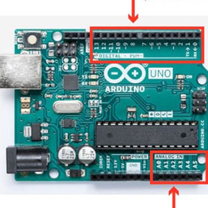
Arduino has socket-like terminals arranged one above the other as an interface for connecting and controlling electronic components. Various controls are possible, such as connecting an LED or motor here to control the operation, connecting a switch or the like to determine on/off, or connecting a temperature sensor to measure the room temperature.
Arduino UNO has 14 (0 to 13) “digital input/output” terminals on the top and six (A0 to A5) “analog input” terminals on the lower right.
The digital input/output terminal outputs have two states: “high state” and “low state,” to operate the electronic component and check the voltage state.
On the other hand, the analog input is a terminal that can input a continuous voltage change. A number is assigned to each terminal, and this number is specified when the electronic components are controlled by the program.

Digital output is an interface that can change the state of each pin from a program. You can freely switch between two states: “High” or “Low.” For example, if an LED is connected and the voltage is high, the LED will turn on. Conversely, if the voltage is low, the LED can be turned off.

In Arduino, when the voltage is high, the terminal voltage is “5V,” and when it’s low, it switches to “0V.” The high voltage state is called “HIGH” and the low voltage state is called “LOW.” When specifying by program, specify “HIGH,” “LOW.” Digital input and analog input will be introduced later in this series.
Let’s turn on the LED by controlling the digital output with a program. This section describes how to turn on the LED connected to the 13th digital input/output terminal. Create the program as follows. Create a program, write it to Arduino as explained previously, and check that the LED lights up.
Lines 4 and 8 are important when controlling digital output. In digital input/output, there are two methods of use: “digital output” that can change the terminal status and “digital input” that reads the terminal status. For this reason, it’s necessary to specify in advance the setting to use. This setting is “pinMode ()” on the 4th line.
pinMode( LED_PIN, OUTPUT );
In pinMode (), specify the target pin number and the mode to be used in parentheses. This time, since the 13th terminal is used, the target terminal is “13,” and when using the digital output mode, specify “OUTPUT.” However, since the terminal number is set to be used with the name “LED_PIN” this time, the target terminal number is specified as “LED_PIN” (described later).
The output is changed by “digitalWrite ()” on the 8th line.
digitalWrite( LED_PIN, HIGH );
Specify the terminal number of the target whose output is to be changed and the order of output to the terminal. The pin number is specified as “LED_PIN” like pinMode (). If the terminal status is specified as “HIGH,” 5V is output. If you connect an LED this time, electricity will be supplied, and the LED will light up. If you want to turn off the LED, specify “LOW” so that the terminal becomes 0V.
This section describes the contents described in programs other than digital output. The following description on the first line names the terminal number to which the electronic component is connected.
const int LED_PIN = 13
The interface that connects the electronic components to the Arduino is numbered. For example, “13” is assigned to the terminal to which the LED was externally connected last time. When actually controlling the LED, the number of the connected interface must be specified by the program. However, if you write the number directly on the program, it’ll be difficult to figure out what the number is, and it’ll take time to investigate if you modify the program later. Also, if the connection destination is changed, it’s necessary to change the location where all the interface numbers in the program are specified, which takes time and may cause other parts to be changed accidentally, resulting in possible malfunction.
Therefore, give a descriptive name to the interface number to which the electronic component is connected. Here, the name “LED_PIN” (variable name) is defined, and “13” is stored in the variable. After this, write “LED_PIN” if you want to control the LED. Note that “int” in front of the variable name represents an integer, and “const” prevents the variable contents from being changed in the program.
The following parts of the 3rd to 5th lines are called the setup () function that’s executed only once.
void setup() {
:
}
When Arduino is turned on, it’ll be executed according to the program written in it. At this time, the program described in the setup () function is executed only once. For this reason, the setup () function is used for initial settings. This program is used to set the mode of the digital input/output terminals.
The following part of the 7th to 9th lines is called the loop () function that executes repeatedly.
void loop(){
:
}
When the program in the setup () function is finished, the loop () function is executed. When the end of the loop () function is reached, the program returns to the beginning of loop (), and the program is executed again. The main body of the program such as LED lighting and motor control should be described here. In this program, the digital output is switched, and the LED lights up.
Let’s learn the meaning of some basic electrical terms. When you select electronic components, or when you’re working with electronics, knowing the electrical terms will help you work smoothly. The first electrical term to remember is “current.”
Among metals, there’s positive static electricity called “positive charge.” Since static electricity is hard to understand, it’s better to think of positive charges as positive particles of electricity as shown in the figure.
This positive charge is supplied from a battery or other power source, passes through the conductor, and flows into an electronic component such as an LED. “Current” represents the amount of positive charge flowing in metal. If a lot of positive charges flow, electronic parts such as LEDs will be able to use a lot of electric power (energy) and shine brighter. Conversely, if the current is small, less positive charge is supplied, so if it’s an LED, it’ll illuminate darkly.
The unit of current is “A (Ampere).”
In addition, negatively charged electric charge is called “negative charge,” but in general, in an electronic circuit, we consider the state where a positive charge is moving through the circuit.

Another electrical term to remember is “voltage.” Positive charges in metal are the source of electricity. This positive charge can be moved by applying electrical force. The force that moves this positive charge is called “voltage.” If the voltage is large, many positive charges can be moved, resulting in a large current. On the other hand, when the voltage is small, the amount of positive charge that moves is small, so the current is small.
The unit of voltage is “V (volt).”
It’s possible to supply 1.5V for batteries, 5V for Arduino power terminals, and 120V for household outlets.

Many electronic components have a limit on the maximum current that can be passed, and will break if more current is passed. For example, if a current larger than the current that an LED can withstand is applied, the LED may emit smoke or become hot and eventually break. A broken LED cannot be used again. There’s also a risk of burns by touching a hot LED.
For this reason, it’s important to adjust the amount of current flowing through the electronic components. A resistor is used to limit this current. Resistors are electronic components that block the flow of electricity and make it difficult for positive charges to flow inside. Since the current is suppressed by the resistor, the amount of current that flows through the electronic component is also reduced, and it operates safely.

For resistance, the degree of inhibition of positive charge flow is indicated as “resistance value.” The smaller the resistance value, the more positive charge flows and the larger the current. Conversely, if the resistance value is large, the current will be small. The unit of resistance value is “Ω (Ohm).” The resistance value, voltage, and current can be expressed by the formula according to “Ohm’s Law.” When a voltage is applied to both ends of a specific resistor, the value obtained by dividing the voltage by the resistance value is the current value that flows.

For example, if a 1kΩ resistor is connected to the Arduino 5V terminal, the following formula is used. 1kΩ is 1000Ω.
5V ÷ 1000Ω = 0.005A = 5mA
Conversely, if you want to pass a specific current, you can also determine the connected resistance value. In this case, it can be found by dividing the value of the current you want to flow from the applied voltage. For example, to apply a current of 10mA when a voltage of 5V is applied, the following formula is used. 10mA is 0.01A.
5V ÷ 0.01A = 500Ω
You can read more about Ohm’s Law here: Learn About Ohm’s law, GPIO, and transistors by simple LED circuit on Raspberry Pi
The resistor has four or five color bands printed on the side. You can know the resistance value from this color band. The color bands have the meanings shown in the following table. The first and second numbers are two-digit numbers, and the third number is a two-digit number. The fourth shows the resistance error.

For example, a resistor printed as “Brown Black Red Gold” can be seen as a 1 kΩ resistor.
When using an LED, it’s necessary to connect an appropriate resistor to light it. It’s possible to calculate how much resistance is connected by simple calculation. When an LED and a resistor are connected in series and a power supply is connected at both ends, the resistance value is calculated using the following formula.

The power supply voltage specifies the power supply voltage of the connected battery. When connecting to the Arduino digital output, specify 5 as 5V is output when HIGH. For the current and voltage flowing through the LED, use the values of “Forward voltage (Vf)” and “Forward current (If)” described on the electronic component sales site and data sheet. If the current flowing through the LED is set to the forward current value, the voltage at both ends indicates the forward voltage. For example, in the case of the red LED “SLR-56VC3F,” the forward voltage is described as 2V (the column of the forward voltage Vf of the electro-optical characteristics) and the forward current is 10 mA (the column of the If of the electro-optical characteristics). Calculate by applying this value to “LED voltage” and “LED current.” If the power supply voltage is 5V, the LED voltage is 2V, and the current is 10mA, the resistance value is found as “300Ω” as shown below.
(5V – 2V) ÷ 0.01A = 300Ω
Also, if you want to light it darker than this, decrease the current value. At this time, the LED voltage hardly changes, so use the value of the forward voltage. For example, when a current of 1 mA is passed, calculate as follows.
(5V – 2V) ÷ 0.001A = 3000Ω = 3kΩ
Let’s connect the LED using the resistance of the calculated value. If there’s no exact resistance obtained by calculation, use a resistance with a close value. For example, if the calculated value is 900Ω, use a 1kΩ resistor with a close value.
This time, we explained the digital output method, voltage, and current. Next time, let’s change the brightness of the LED.