![]()
Originally published by Feb 4, 2020
This article was translated to English, and was originally published for deviceplus.jp.
In this article, you can learn how to use tact switch in your Arduino project and how it actually works.
The digital output enables you to control the LED and motor, switching the digital output pin between two states, HIGH (5V) and LOW (0V).
You can also use the output to check the electronic components. The digital output pin can be switched to the digital input. By doing this, you can check the voltage applied to the pin with input in two ways, “LOW” and “HIGH”. These input values can be used to control other electronic components. For example, you may want to operate the motor when the digital input is HIGH or stop it when the input is LOW.

Actually, the state of the digital input pin is switched to 0V or 5V using an electronic component such as a switch.
This time we will describe how to implement digital input using a switch.
With Arduino Uno, you can assign any of the pins D0 to D13, originally used for digital output, as digital input. The pin states can be checked by switching to the digital input mode programmatically.
The input is “LOW” at 0V or “HIGH” at 5V. The program reads “0” as LOW and “1” as HIGH. You can use these input values to control the operation via processing such as conditional branching after checking them.

Let’s actually try digital input with Arduino. Here, let’s check the change when connected to the 5V power supply and GND using a jumper wire for pin 5. Create the following program and write it to Arduino:
In line 4, specify “INPUT” in pinMode() to switch pin 7 used this time to the input mode. You can now check the pin state from the program.
The pin state specified in digitalRead() on line 11 is acquired and stored in the value variable. “0” is stored if it is 0V or “1” if it is 5V.
Use the “serial monitor” when you want to check the acquired status. With Arduino, you can send the data from Arduino to a PC using the USB cable used to transfer the program from the PC. Serial communication is used to exchange the data. You can use serial communication to check the state acquired by digital input by sending it to the PC.
If you want to use serial communication in the program, initialize it with Serial.begin() (line 5). Specify the communication speed here. You can send data to the PC by specifying a value in Serial.println() (line 12). This time it sends the content of the value variable that stores the state of the digital input.
To check the data sent from Arduino via serial communication, use the “serial monitor” built into the Arduino IDE. To use the serial monitor, click the “serial monitor icon” (magnifying glass icon) in the upper right corner of the Arduino IDE. The serial monitor screen is then displayed. Set the communication speed in the lower right to the same value as the communication speed specified in Serial.begin() of the program (9600 here). Then, 0 or 1 is displayed on the screen.

Next, insert a jumper line into pin 7. Connect the other end to GND, and “0” is shown on the serial monitor. That is, you can see that the state is “0” (LOW) if the pin is 0V. Similarly, you can see that the display switches to “1” (HIGH) when connected to pin 7 and the 5V power supply.

We have now confirmed that the input changes depending on the pin state.
Now, let’s use a switch to shift the digital input pin between HIGH and LOW. Use the push-button “tact switch” here.

In the tact switch, when the top button is pressed, the internal circuit is connected and electricity flows through. When the button is released, the circuit is disconnected and electricity will not flow through. In general, the switch has pins mounted at the four corners. When arranged as shown in the figure above, the gap between the right and left pins works as a switch. The upper and lower pins on the right side and the left side are always connected.
Press the switch with one end of the tact switch connected to the pin and the other end to GND; the internal circuit is connected, connecting the pin directly with GND. By doing this, you can see that the digital input is “HIGH” by pressing the switch.

However, when the switch is not pressed, it means that nothing is connected to the pin. In such a case, the voltage applied to the pin becomes unstable. If it is unstable, the input may change if you touch the pin or put a battery close to it.
Therefore, we connect a circuit called a “pull-up” or “pull-down” circuit when using the switch. This method stabilizes the state by connecting the pin to the power supply or GND via a resistor. The circuit is called a pull-up circuit when connected to the power supply and a pull-down circuit when connected to the GND side. Here, we use an example with a pull-up circuit for explanation, but the principle is the same for a pull-down circuit.

When using a pull-up circuit, the switch is connected to the power supply via a resistor when the switch is not pressed. It is the same state as when the pin is connected to the power supply, and the input is stabilized at 5V (HIGH). With the switch pressed, the pin is directly connected to GND, so the input switches to 0V (LOW).
Though the power supply and GND are connected, a resistor is sandwiched between them, therefore a small amount of current (generally about 10 kΩ) flows, so there is no risk of short circuit.
Now, let’s actually input data using the tact switch. Prepare the following electronic components.
・ Tact switch

Tact switches are available in various colors. You can select any color that you like.
・ Resistor 10kΩ (1/4W)

Resistor used for a pull-up circuit. The color code “brown-block-amber-gold” is printed on 10kΩ resistors.
When you have prepared the components, connect them as shown in the figure below. Insert the tact switch across the groove in the center of the breadboard.
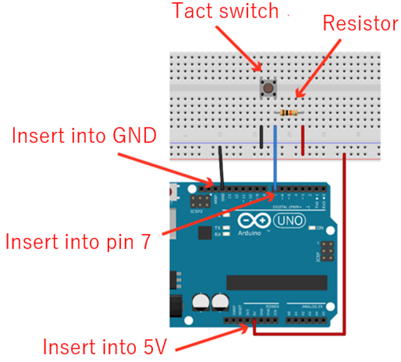
Next, write the program described earlier to Arduino to check the input of pin 7 in the serial monitor. The value “1” (HIGH) is displayed when the switch is released, and the value changes to “0” (LOW) when the switch is pressed.
In Arduino Uno, the pins are equipped with a “pull-up” function, which can be activated programmatically. The internal pull-up eliminates the need to connect an external resistor. You only need to connect the switch, thus saving time and effort.

Write the following program to activate the pull-up:
You only have to specify “INPUT_PULLUP” in the pin mode setting (line 4). It activates the built-in pull-up, thus stabilizing the HIGH input when the button is not pressed. Note that the pull-down is not installed.
The switch input can be used to control other electronic components. So, let’s use the LED installed in Arduino (pin 13) to turn on the LED when the switch is pressed, and turn it off when the switch is released. We use the same circuit as that used to connect only the switch to the pin as described earlier. Write the following program:
Line 14 checks if the value digitally input is “1”. In Arduino programs, you can write “1” as “HIGH” and “0” as “LOW”. It is a good practice to use “HIGH” and “LOW” since they are easy to understand.
If the input is HIGH (button not pressed), line 15 is executed, switching pin 13 to LOW and turning off the LED. If the input is not HIGH (button pressed), line 17 is executed, switching pin 13 to HIGH and turning on the LED. When you write the program to Arduino and press the tact switch, you can see that the LED is turned on.
And there we go! Now you can perform input using a switch in your Arduino project.
Explore the rest of this series to get to know about the basics of Arduino:
 The Basics of Arduino: Adjusting LED Brightness
 The Basics Of Arduino: Control LED Lighting with Digital Output
 The Basics of Arduino: Reading Voltage
 The Basics of Arduino Electronics: Controlling the Motor
 What Is Current, Voltage, Resistors, and Ohm’s Law?
 Use Arduino to Control a Motor Part 4 – Adding a Remote Control and Using Arduino pro Mini for Miniaturization


