![]()
Did you know that the Raspberry Pi was never intended for use in hobby electronics and prototyping?
According to a recent interview with creator Eben Upton, the decision to connect the Broadcom chip’s GPIO pins to a 40 pin header was really an afterthought. At the time, he wasn’t much convinced that anyone would use it.

Arduino boards, on the other hand, are built for little else but electronic prototypes, which is why they come with quite a bag of tricks. Key among these are its usefulness in working with analogue voltages: those voltage levels that aren’t all the way on, or all the way off, but somewhere in the middle.
Connecting an Arduino Uno to your Raspberry Pi’s I2C bus is a great way to add these analogue voltage capabilities to your Raspberry Pi project.

This follows on from part 1 of our guide to using I2C to connect a Raspberry Pi to an Arduino Uno.
PWM – or pulse width modulation – is a way of varying the amount of power a pin provides by switching it off and on really fast.
This isn’t a true analogue voltage, but for something like dimming an LED, you’d never notice the difference.
For tasks that require more power than the PWN pin can provide directly, you can use it with a transistor. With this arrangement, you can vary the speed of a DC motor.
The Raspberry Pi has two hardware PWM pins and if that’s all you need, great! Be aware that the Raspberry Pi uses the same PWM hardware for the built-in analogue headphone output, so it’s not a great idea to use them simultaneously.
You can also use software to generate a PWM signal from any GPIO pin. The disadvantage of this is that it puts you at the mercy of the operating system, which may introduce tiny interruptions as it juggles tasks. That’s fine when there are no grave consequences for the occasional small inaccuracy. For a robot or industrial machinery, it’s not so great.
The Arduino Uno has six hardware PWM pins. If you still need more, the Arduino Mega offers 15.
And because this is I2C, if one microcontroller isn’t enough, you can connect a hundred more to the same bus.
Ok, let’s put this into practice.
The Arduino IDE makes PWM easy using the analogWrite() function. This takes two arguments: the first is the pin number, and the second is a value between 0 (for always off) and 255 (for always on).
You don’t need to import anything to use analogWrite(). Be sure that you are using it with a pin that connects to PWM hardware. On the Arduino Uno, those pins are 3, 5, 6, 9, 10 and 11.
We can read the I2C bus for analogWrite() values like this:
#include
const int led = 9;
const int addr = 0x8;
void setup() {
// Joins the I2C bus as a slave at address 0x8
Wire.begin(addr);
// Sets pin 9 as an output pin
pinMode(led, OUTPUT);
// Calls the changeBrightness function when the master sends a value
Wire.onReceive(changeBrightness);
}
// Reads and sets the PWM value from the I2C bus
void changeBrightness(int bitstream) {
int brightness = Wire.read();
analogWrite(led, brightness);
}
void loop() {
}
Upload this sketch to your Arduino Uno and then connect it to the Raspberry Pi’s I2C, ground and power pins, just as we did in part 1.

Then, like we did in part 1, connect an LED and a 680-ohm resistor in series to pin 9 and then complete the circuit to ground. Remember that the anode (the longer leg) on the LED connects to positive.

Now we can use the smbus module to connect to the I2C bus. Again, it’s the same as what we learned in part 1.
from smbus import SMBus
arduino = 0x8
i2cbus = SMBus(1)
Just like before, we can use the write_byte method to write values to the I2C bus.
i2cbus.write_byte(arduino, 180)
i2cbus.write_byte(arduino, 35)
i2cbus.write_byte(arduino, 250)
i2cbus.write_byte(arduino, 120)
Does this alter the brightness of the LED? If so, great!
What if a PWM signal isn’t enough, and you want a genuine analogue voltage? One option would be to use a different Arduino board, such as the Arduino Duo or Arduino Zero, which have pins that can do this.
It’s also incredibly easy to turn the PWM signal into a true analogue voltage by using a low pass filter to smooth it. A low pass filter can be as simple as a single resistor and capacitor.
Which resistor and capacitor? Well, it’s a tradeoff. Higher values, you will better filter out the ripple from the PWM signal but add a lag to adjust to a change in the output. We’re talking nanoseconds and milliseconds of lag, but sometimes that matters. You can delve into the nitty gritty here.
For this project though, let’s keep things dirt simple. We’ve already got working code to control the PWM value – let’s reuse it here. Let’s build a low pass filter built from a 4.7k resistor and a 100nF ceramic capacitor.
That starts by removing the LED and resistor from the breadboard. We’re done with them now.

Connect one end of the resistor to pin 9 of the Arduino Uno. Then connect one leg of the ceramic capacitor to the other end of the resistor, and the other leg of the capacitor to ground.

Now use the highest value resistor you have handy to complete the circuit to ground. Anything in the Megaohms range is great. Using a value this high means the voltage drop from the 4.7k resistor in our filter is negligible.

Now, use the same commands in the Python interpreter we used before to vary the PWM value. Use a multimeter to measure the voltage between the low pass filter and ground.
With a value of 255, it should read very close to 5 volts. A PWM value of 127 will give you 2.5 volts, and so forth. Have a play around to see the differences!
The Raspberry Pi’s on-board capabilities with PWM are limited. When it comes to reading analogue voltages, it has no on-board capability at all.
By contrast, the Arduino Uno has six ADC (analogue-to-digital converter) channels, although we’re using two of these pins for the I2C bus. They offer a 10-bit resolution, which means they convert the voltage on the pin to a value between 0 and 1023.
Have you never used these pins on the Arduino Uno before? Before going any further, check out the example projects in the file menu: particularly AnalogReadSerial and ReadAnalogVoltage. There are clear instructions commented into the code.
We’re about to do something very similar here, we’ll just use the I2C bus.
All the things we did before to use the I2C bus to set PWM values have a corresponding operation.
We join the I2C bus as a slave in the exact same way. Then, instead of using Wire.onReceive() to specify how to handle a command, we use Wire.onRequest() to specify how to handle a request. Instead of using Wire.read() to read a value from the I2C bus, we use Wire.write() to write a value to it. And instead of using the analogWrite() function, we use analogRead() to read the analog value from.
You can put that all together like this:
#include
void setup() {
// Join I2C bus as slave with address 8
Wire.begin(0x8);
// Call the sendReading function when data is requested
Wire.onRequest(sendReading);
}
// Reads the value from pin A0 and then writes it to the I2C bus
void sendReading() {
int reading = analogRead(A0);
Wire.write(reading);
}
void loop() {
delay(100);
}
Upload this sketch to your Arduino Uno.
First, remove the resistors and capacitor from the last example, and disconnect pin 9 from the breadboard too. We’re done with that now.

Then place a potentiometer (it doesn’t matter what value) on the breadboard and connect the center pin to pin A0 on the Arduino Uno.
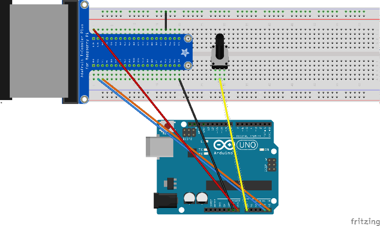
Complete the circuit by attaching the other pins to 5 volts and to ground.
Instead of using a write_byte() method to write to the I2C bus, we use a read_byte() one to read from it. This method takes the I2C address as an argument and returns the value it reads. Try it:
i2cbus.read_byte(arduino)
Turn the potentiometer to change the voltage on the pin and then run the command again.
What we’ve covered here is fine for reading or writing a single byte of data. You may wish to do more than this, using functions and methods we haven’t explored here.
If so, feel free to check out the documentation for the Arduino Wire Library and for Python’s SMBus module!
 Building a Wavetable Synthesizer with a Raspberry Pi and an Arduino Uno
 How to Find Out When Your Plants Need Watering with a Soil Sensor
 Low Power Arduino Hack Guide #2: Energy Optimization Design Methods
 Connecting a Raspberry Pi to an Arduino Uno
 How to Use a Relay to Control Lamp or Other High-Voltage Electronics
 Arduino Communication Protocols Tutorial


