![]()

This article is another piece in our series about using “Arduino with parts and sensors.” This time, we will try using a stepper motor, which is often used in robot arms and wheeled robots tires. What kind of new possibilities open with a stepping motor? We will operate the stepper motor while learning about its properties and try to figure out what ways it can be used.
Expected time to complete: 90 minutes
Parts needed:

Picture 1 Stepper Motor
Stepper motors are different from the servomotors and standard motors we have introduced until now. By sending electronic signals into the motor, we can control the motor’s rotation. Looking generally at the motor characteristics, we get something like:
How does this stepper motor operate? Let’s check Wikipedia.
Stepper Motor – Wikipedia
A stepper motor or step motor or stepping motor is a brushless DC electric motor that divides a full rotation into a number of equal steps. The motor’s position can then be commanded to move and hold at one of these steps without any feedback sensor (an open-loop controller), as long as the motor is carefully sized to the application in respect to torque and speed.
This electronic signal called a “pulse” is the key to operating our stepper motor.
The keyword “pulse” is a word most people have heard of one place or another, but not necessarily when dealing with electrical circuitry. When talking about circuits, pulse typically refers to periodically spaced square wave pulses, which are waves produced from the on-off or high-low variations in power.

Figure1 An example of a pulse signal
By switching power on and off at a fixed width, a variety of parts can be moved. This process is called PWM (Pulse Width Modulation); it is an often-heard keyword when working with electrical motors. The commonly-used analogWrite() function for the Arduino is produced by PWM signals.

Figure2 PWM signal
We used analogWrite() earlier in this series to control the brightness of LEDs. The maximum output voltage per pin for the Arduino UNO is 5V, but the output value (0-255) designated by analogWrite(pin, value) does not actually produce 5V divided into 256 parts. Instead, the Arduino’s pulse cycle takes an average of 5V time and 0V time to generate a pseudo-output similar to analog voltage. Until now, we have been using PWM without knowing it.
* For example, an input of analogWrite(PIN, 128) does not produce a voltage of 2.5V from the pin. Instead, half of the cycle period is at 0V and the other half is at 5V for an average of 2.5V.
The stepper motor itself can be controlled simply with PWM, but it is difficult to directly send signals from the Arduino to a stepper motor. Today we will be using a motor driver kit called L6470 to easily control the stepper motor.

Picture2 L6470 Motor Driver Kit

Picture3 Parts Set
This driver kit set requires several parts to be soldered onto a circuit board. If you follow the accompanying manual, it should not be a problem.
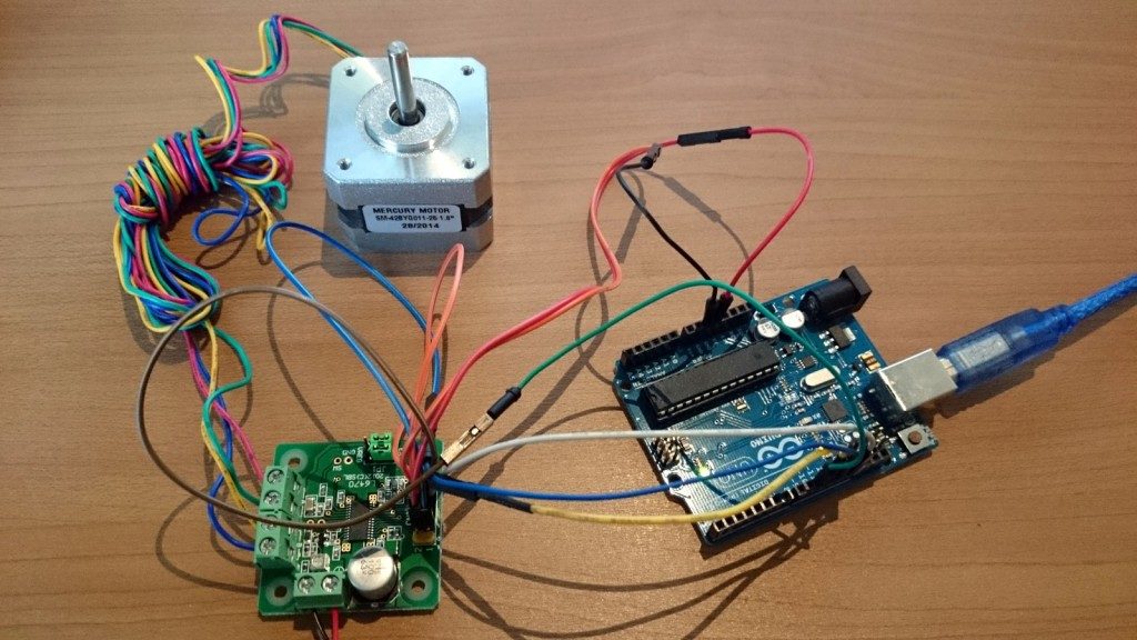
After soldering, we connect Arduino, the stepper motor and the driver kit. This time, we attached a 12V 1.5A AC adapter to the 8V-48V part of the motor.

Figure3 Stepper Motor Circuit
After connecting Arduino, the stepper motor and the driver kit, we can then prepare our program.
In today’s sample program, the entire set of command functions are input by a file in a separate tab in Arduino, so when making programs using files, don’t forget to add this command file.
Stepper Motor Operation Program
|
1 2 3 4 5 6 7 8 9 10 11 12 13 14 15 16 17 18 19 20 21 22 23 24 25 26 27 28 29 30 31 32 33 34 35 36 37 38 39 40 41 42 43 44 45 46 47 48 49 50 51 52 53 54 55 56 57 58 |
#include #include // Define pins. #define PIN_SPI_MOSI 11 #define PIN_SPI_MISO 12 #define PIN_SPI_SCK 13 #define PIN_SPI_SS 10 #define PIN_BUSY 9 void setup() { delay(1000); pinMode(PIN_SPI_MOSI, OUTPUT); pinMode(PIN_SPI_MISO, INPUT); pinMode(PIN_SPI_SCK, OUTPUT); pinMode(PIN_SPI_SS, OUTPUT); pinMode(PIN_BUSY, INPUT); SPI.begin(); SPI.setDataMode(SPI_MODE3); SPI.setBitOrder(MSBFIRST); Serial.begin(9600); digitalWrite(PIN_SPI_SS, HIGH); L6470_resetdevice(); //L6470 Reset L6470_setup(); //L6470 Setup MsTimer2::set(50, fulash); //Interrupt serial monitor timer MsTimer2::start(); delay(4000); } void loop(){ <span style="color: #ff0000;"> L6470_move(1,500); //Normal L6470_busydelay(500);</span> //Wait 2 seconds } void L6470_setup(){ L6470_setparam_acc(0x40); //[R, WS] Accelerate default 0x08A (12bit) (14.55*val+14.55[step/s^2]) L6470_setparam_dec(0x40); //[R, WS] Decelerate default 0x08A (12bit) (14.55*val+14.55[step/s^2]) L6470_setparam_maxspeed(0x40); //[R, WR] Maximum speed default 0x041 (10bit) (15.25*val+15.25[step/s]) L6470_setparam_minspeed(0x01); //[R, WS] Minimum speed default 0x000 (1+12bit) (0.238*val[step/s]) L6470_setparam_fsspd(0x3ff); //[R, WR] μ Step to full-step conversion speed default 0x027 (10bit) (15.25*val+7.63[step/s]) L6470_setparam_kvalhold(0x20); //[R, WR] Stopped excitation voltage default 0x29 (8bit) (Vs[V]*val/256) L6470_setparam_kvalrun(0x20); //[R, WR] Fixed rotation excitation voltage default 0x29 (8bit) (Vs[V]*val/256) L6470_setparam_kvalacc(0x20); //[R, WR] Acceleration excitation voltage default 0x29 (8bit) (Vs[V]*val/256) L6470_setparam_kvaldec(0x20); //[R, WR] Deceleration excitation voltage default 0x29 (8bit) (Vs[V]*val/256) L6470_setparam_stepmood(0x03); //Step mood default 0x07 (1+3+1+3bit) } void fulash(){ Serial.print("0x"); Serial.print( L6470_getparam_abspos(),HEX); Serial.print(" "); Serial.print("0x"); Serial.println( L6470_getparam_speed(),HEX); } |
This time we were able to operate a stepper motor. Next time, we will try using a stepper motor to make a device.