![]()
Question: There seems to be different methods for current regeneration operation with PWM drive in the off-duty period. What are they?
Answer: There are two main methods. The first involves shorting 2 terminals of the brush motor, while the second entails connecting the 2 pins to the power supply (+/-) in the on-duty period. The former provides gradual attenuation of the regenerative current, while the latter attempts to supply voltage to the coil in the reverse direction of current flow, resulting in sudden attenuation of the regenerative current. With the short circuit method, the approximate voltage supplied to the motor is simply the Supply Voltage x ON Duty Ratio, but with the ON duty period method the voltage supplied the voltage is calculated by: Supply Voltage x (ON Duty Ratio – 50%)/50%.
With this method, in the event the ON duty drops below 50% current will flow in the reverse direction as if connected by turning ON the output MOSFET, and the voltage is determined by the ON duty ratio supplied to the motor. However, turning OFF all output MOSFETs will cause no current to flow (as if connected to a parasitic diode), resulting in a small amount of current flow in the positive direction due to the ON duty ratio – even if less than 50%.
Equivalent current regeneration circuits for both methods (short-circuit, ON duty period) during PWM current supply are shown in Figure 1 below.
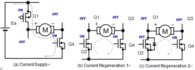
Figure 1. Current pathways during current supply and current regeneration with PWM drive
When current is supplied, Q1 and Q4 are turned ON, connecting the motor to the power supply. During the current regeneration shown in 1(b), Q1 is turned OFF, Q2 is turned ON, Q4 remains ON, and the motor current cycles through the parasitic diode of Q2.
The PWM operation waveforms for implementing current regeneration that shorts the 2 motor terminals are shown in Figure 2.
However, do note that the change in peak-to-peak current can be larger than during actual operation.

Figure 2. PWM operation current regeneration waveforms with motor 2-pin shorts
When the generated voltage (Ec) of the motor is zero the average current value Iave is:
Iave=Ea•m/R
(with Ea: Motor Supply Voltage, m: ON Duty Ratio, and R: Motor Equivalent Resistance)
The voltage multiplied by the ON duty ratio of the motor supply voltage is supplied to the motor.
The equivalent circuits connecting both motor pins in reverse in the ON duty region for current regeneration are shown in Figure 3.

Figure 3. Current regeneration circuits with both motor pins connected in reverse during PWM drive
In the circuit for Current Regeneration 3 shown in (d) above, Q1 and Q4 are turned OFF, Q2 and Q3 are turned ON, and the power supply polarity supplied to the motor and ON duty period are reversed. In (e) above all of the transistors from Q1 to Q4 are turned OFF, but current is regenerated and flows through the parasitic diodes of Q2 and Q4, resulting in reverse power supply polarity applied to the motor and ON duty period.
The PWM drive waveforms of the circuits shown in Figure 3 where reverse current flows due to reverse polarity of the motor terminals and ON duty region are shown in Figure 4 below.

Figure 4. PWM drive current regeneration waveforms when current flows in the reverse direction in a circuit where the both motor terminals are connected in reverse polarity with the power supply
When the regenerative current falls below zero current will flow in the reverse direction, resulting in an average motor current of zero at 50% ON duty. With an ON duty of 50-100%, current will flow in the direction of the average current, while in the 0-50% range current will flow in the opposite direction if over 50%. The voltage supplied to the motor is calculated by:
Motor Supply Voltage x [ON Duty Ratio (%) – 50%]/50%
Figure 5 below shows PWM drive waveforms when the current does not flow in reverse in a current regeneration circuit like the one shown in Figure 3(e) (with reverse power supply connection).

Figure 5. PWM drive current regeneration waveforms when reverse current does not flow in a circuit where both motor terminals are connected in reverse polarity with the power supply
Because the current does not flow in reverse during the ON duty period, the average current will not be zero, even with an ON duty ratio of 50%, but when the ON duty drops below 50% the average current will also decrease and the current will drop to zero. The voltage supplied to the motor in the case the minimum peak current value with transient current waveforms is larger than zero will be:
Motor Supply Voltage x [ON Duty Ratio (%) – 50%]/50%.
And because there are differences between the equivalent voltages and high-side output transistor and low-side ON resistance along with forward voltage generated in the diode under actual conditions, some deviations in the above equations will occur.


