![]()

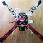
Today we will turn some readily available components into a quadcopter capable of taking high-quality aerial photos and stabilized HD video. The craft will also include safety features so new pilots can feel confident flying the quadcopter. A live video stream from the quadcopter is delivered to a mobile device from a Raspberry Pi over WiFi. Having a Linux computer aboard the drone also presents you with many opportunities—additional sensors, computer vision, etc.
In the first part of this series we will go through the hardware of the quadcopter—what parts you need, what each part does, and how to assemble each part. In the second and third part of this series we will go through the software of the quadcopter—enabling fail safes, remote control, and flight modes.
Before starting this project it is imperative to understand the purpose of each part of the quadcopter. Below is a list of each part on the quadcopter you will build, its purpose, and the specific part used in this How-To.
Step #1: Solder ESCs to bottom plate
The DJI F450 frame that we are using has a top plate and a bottom plate, which when assembled “sandwich” the arms between them. Each of the four arms will hold a motor at the end of the arm and an ESC under the arm. Together the two plates hold the four arms together and provide a mounting surface for all the components we will be installing on the quadcopter.

Figure 1: DJI Flamewheel frame bottom plate / ©QuadcopterGarage
The bottom plate has a very important function—it distributes the battery’s power to all the ESCs. As you can see in the picture above there are five pairs of positive and negative pads—one for each ESC and one for the battery connector. Each ESC (electronic speed controller) has two cables coming from its casing: a two wire PWM cable and a larger black power cable.

Figure 2: Electronic Speed Controller (ESC)
We are concerned with the power cable now—the PWM cable will be connected to the flight controller later. The power cable is much longer than we need it, it can be snipped to about 12cm long. Then cut off some of the black insulation from the cable to reveal a red wire (positive) and a bare wire (negative). Solder the red wire to the pad with the (+) and the bare wire to the pad with the (–). To help prevent any short-circuit I covered the pads with hot glue. Repeat this process for each motor.
Step #2: Solder the voltage regulator and battery wire to bottom plate
After soldering the ESCs to the bottom plate there will still be one pair of pads with nothing connected to them (the pads at the bottom in Figure 1). These pads are where we connect the battery wires and the wires for the voltage regulator (Figure 3).

Figure 3: The voltage regulator is the small black rectangle between the two white legs
Included in the NAZA-M Lite box should be two large gauge wires—a red one and a black one. Solder the provided red wire and the red wire from the voltage regulator to the positive (+) pad. Solder the provided black wire and the black wire from the voltage regulator to the negative (–) pad. To help prevent short-circuits I covered the solder pads with hot glue.

Figure 4. The battery and voltage regulator wires soldered to the power distribution board
Step #3: Attach T-connector
Now we can’t directly solder the battery to these wires; if we did so we would not be able to swap out batteries or charge them. So to connect the battery to the power distribution board in the bottom plate we will solder a male T-connector to the two wires we just soldered. To do so place the connector short-side up, and solder the red wire to the short horizontal part and the black wire to the short vertical part (see connector on right in the figure below for polarity).

Figure 5: Polarity of T-connector / ©Ruberkon
When you finish soldering you should have something that looks like this (I covered the exposed contacts with electrical tape, however, you can also use heat shrink):

Figure 6: The T-connector we use to connect the battery
Step #4: Attach the flight controller

Figure 7: The NAZA-M Lite flight controller / ©djicdn.com
Take the black double sided tape provided with the NAZA-M Lite and cut off a piece about as long as the flight controller. Peel the protective wrap off one side of the tape and firmly affix it to the middle of the bottom plate. Then take your flight controller and orient the side that has multiple labels of M1,M2, M3, etc. towards the side of the bottom place you decided is the front of the quadcopter. Remove the protective wrap off the other side of the tape and affix the flight controller to the tape.
Step #5: Mount RC receiver
I choose to mount my RC receiver to the bottom of the lower plate extension on the back of the frame. Simply attach it with hot glue or double-sided tape. The wire that extrudes from the receiver is the antenna—leave it alone until we assemble the legs.

Figure 8. The receiver is placed underneath the back of the frame
Step #6: Attach servo cables from receiver to flight controller
Each column of three pins on the receiver outputs a PWM signal. In the RC world, each of these PWM signals is called a channel and represents one component of the pilot’s commands. For example channel 3 on the receiver is the pilot’s desired throttle. For the flight controller to receive each of the pilot’s commands we must use a PWM cable to connect each channel on the receiver to the flight controller. Note that the orange (signal) wire on the PWM cable should be on the top when inserted into the flight controller, and the other end of the brown cable should face downwards when connected to the receiver.

Figure 9. The PWM cables connected to the receiver. Notice how the cables are inserted so that the orange wire is on top.
You should attach the PWM cables as follows (where the channel number on the left is written on the receiver and the letter in parentheses on the right is written on the back of the NAZA):
Step #7: Attach ESC servo cables to flight controller
Remember those servo cables from ESCs I mentioned earlier? Now we will connect them to the flight controller. Connecting the ESC to the flight controller in the wrong order is a common cause of crashes so it is important to get it right the first time.
On the forward facing side of your NAZA-M Lite you will see multiple columns of pins labeled M1–M6; we only have to deal with pins M1–M4. You must connect the motors to the flight controller according to the diagram below where the red arms are the front of the quadcopter. For example, the servo cable from the front right ESC must be connected to M1; the front left ESC servo cable must be connected to M2, and so on moving in a counterclockwise direction.

Figure 10: Numbering of motors assumed by NAZA
Step #8: Attach top plate to arms

Figure 11: Side view of the frame
Now that we have installed all the electronics on the bottom plate it is time to secure the arms and plates together, starting with the top plate. You may have noticed that the DJI F450 frame includes two red arms and two white arms. This is because we can place the two red arms on the front of the quadcopter and the two white arms on the back of the quadcopter so when the quadcopter is in the air we will know where its front is pointed.

Figure 12: Each arm is bolted to the top plate as shown below
Use the bolts provided with the frame to secure each arm to the top plate with four bolts. Make sure that the two red arms are on the side of the NAZA where you connected the ESC servo cables into M1 and M2—this will be the front of the quadcopter. After the next step, you will see that each arm is effectively “sandwiched” between the top and bottom plates.
Step #9: Attach legs and bottom plate

Figure 13: The legs used for the frame
The white legs that came with your F450 ARF kit (pictured above) are used to protect important electronics underneath the quadcopter during takeoff and landing. The legs are attached by using the long bolts provided with the frame. Position the legs so that they run directly underneath the arms and run the bolts through the legs, the bottom plate, and into the bottom of the arm. Make sure that the ESC power cable runs from frame underneath the arch on the bottom part of the arm. Repeat this procedure for each of the four arms.

Figure 14. The legs are placed directly below the arms. Notice how the ESC cables fit between the space in the arm.

Figure 15: How legs are secured to the bottom of the frame