![]()
This article was translated to English, and was originally published for deviceplus.jp.
Devices Plus’ electronic work series has piled up to quite the resource. Many readers have enjoyed reading our past articles and creating things with their own hands.
However, a recent reader has stated, “I can make some things, but I don’t really understand the principle behind it.” Certainly, when it comes to electricity, electronics, circuits, and programs, there are inevitably difficult parts, and it’s sometimes hard to understand the fundamental principles behind them. The editorial department feels the pain at times!
This time, Naomi Ito, who’s active in media art and in the world of books, will be explaining the deeper mechanisms. The theme is blinking LED lights. There is a lot to learn, so let’s get to the most important part. We will be applying what we learn later on, as well.
Over the past few years, small microcomputers have boomed along with electronic work. It feels strange to think that it’s now possible to sense and control various things, including light, sound, movement, and images with a small device in the palm of your hands. I am deeply impressed that the future I imagined when I was a child is slowly coming to fruition.
The image of electronic work has changed from the days of making radio with transistors. Since I’m into media art, the technique for expressing yourself has expanded by treating electronic work as tools and materials, kind of like paintbrushes and paints. In the same way, there are many ways to express art in my surroundings, while on the other hand, enjoying manufacturing as a hobby is called “maker.” When I see related events held in various places, I feel that the concept of a hobby as a subculture has changed.
Now, I enjoy doing electronic work using Raspberry Pi, which is easily accessible even among microcomputers. It also has an OS with a variety of applications installed, and it’s easy to use.
This time we’ll be using the Raspberry Pi 3 Model B+
By “Blinking LEDs,” we are referring to the circuit in which you can see the LED lights flickering on and off. Of course, something as simple as making LED lights blink is easy to re-create using electronic components such as transistors and capacitors. By the way, the circuit that I often use in electronic work is a circuit called an astable multivibrator, which consists of two transistors and two capacitors, four resistors, and one LED, and these are soldered to the board and lit with a dry cell.
Circuit Ex:Astable multivibrator
Work Ex:Reimagined Railway Sign
In this circuit, the LED lights blink alternately at about one-second intervals. To change the flashing speed, change the capacitance and resistance value of the capacitor. To make it flash quickly, change the capacitor capacity to a smaller one.
Now here’s where the microcomputer comes in.
Making an LED light up with the output on a Raspberry Pi is simple and easy to handle using GPIO. This is also introduced in various books, and since there are many dedicated expansion boards with the necessary functions to assemble like blocks, details will be available there. However, some of the most basic knowledge required when building an electronic circuit seems to be important but not explained more in-depth, so let’s review those here. Try to remember those things you learned in science and technology classes during elementary and junior high school.
Ohm’s law is “current = voltage / resistance.” Back in my day, it was written as I = E / R. Now it’s A = V / Ω right?
This formula seems to be close to the times and textbooks, but “A (ampere) = V (volts) / Ω (ohms)” expresses the unit itself and may be more intuitive and easy to understand.
![]()
You can see a diagram like this in the reference book, but try to remember how you learned it. By the way, when I asked the keeper of an acquaintance’s zoo, this is how he learned it.
![]()
“Earth in the Horizon, the seagull in the sky, the octopus and the squid in the sea”
Now, as to how to use Ohm’s law, think of it as simply lighting an LED with a battery. You can connect the LED to the power supply (battery here), but since the LED is a kind of a diode, there’s a direction for the electricity flow: connect A (anode) to the positive side and K (cathode) to the negative side.
![]()
The connection direction is good with this, but in fact, the LED may be broken if it remains as it is. To avoid breaking the part, you must pass the correct electricity through the part.
Correct electricity is within the limits of the rating table (data sheet) for the part. Depending upon the product, for example, in the case of a white LED with a voltage of 3.5V20mA, this electricity can be interpreted as “Unbreakable if within the security scope.” In other words, it’s like saying, “If you use it beyond this, it may break.”
Thus, the optimum voltage to apply to this LED is 3.5V, and the current to flow is 0.02A.
First, if the voltage is 3.5V, consider a higher power supply voltage. For example, consider a 6V power supply with four dry batteries. Strictly speaking, a new battery may have a voltage close to 1.6V. Of course, it’s best to consider so far, but it’s omitted here since it’ll be described later.
Of 6V, I want to apply 3.5V to the LED, so let’s apply the other 2.5V to the other. This can be done by dividing the voltage, so another load is put in series with the LED, but a simple resistor should be connected.
Recall the experiment that the brightness is different from the case where the bulbs are connected in series and in parallel. When the load (bean bulb) is in series, the voltage is divided and the load is doubled, so the current flowing through the circuit is 1/2, and the bulb is dark.
Because the load differs due to individual differences such as the fatigue degree of miniature light bulbs
Divided voltage is called partial pressure. Now, I’ll go back to talking about LEDs. Since LEDs are semiconductors, they’re not considered as loads, so even if they’re divided, the circuit current is calculated outside the LED.
![]()
Since 20mA current should flow through this circuit, how much resistance should I use? This can be calculated using Ohm’s law. Since “resistance = voltage / current,” connect a resistor of 2.5Ω / 0.02A = 125Ω, 125Ω in series with the LED. The voltage is divided by the LED and resistor.
Now, if you look for a resistor of 125Ω, it’s not actually on the market. The closest resistance values are 120Ω and 130Ω. In the case of 120Ω, this is also 25/120 = 0.0208333 when the current is calculated using Ohm’s law. Since it’ll slightly exceed 20mA, use 130Ω. In this case, it’ll be good if it becomes 20mA or less.
Consider the case where a new battery is used. If each were 1.6V, then the total would be 6.4V. If you apply 2.9V to the resistor, it’ll be calculated as 145Ω. So, 150Ω is enough for the product. Of course, the larger one is safer, but the LED gets darker. It’s a good idea to select a model based upon how much is necessary, depending upon the work you’re creating. This resistor is called a current-limiting resistor because it controls the current flowing through the circuit.
Raspberry Pi has many input/output terminals called GPIO that are useful for controlling external devices. As for the details about this, it’s not something that I have written down, so how do I go about explaining about how electrical signals are generated?
![]()
For example, can an LED be lit when connected to this terminal?
Of course it can! However, as noted earlier, LEDs have their respective ratings. For example, when trying to shine a red 2.0V20mA LED, a current-limiting resistor is used. Since the GPIO output voltage is 3.3V, you can divide 1.3V into the current limiting resistor and pass 20mA. However, the Raspberry Pi GPIO can only flow up to 16mA, so if you calculate this with Ohm’s law, it’ll be “1.3V / 0.016 = 81.25Ω,” so I used 100Ω. Although it can’t be said that the LED performance of the rating table is fully demonstrated, it’ll be enough to light it up. You can easily experiment with this on the breadboard.
![]()
This is the best way to make the lights flicker with Scratch.
Declare GPIO, set GPIO4 to output, and then output ON (Hi) to GPIO4.
If you leave it on the left, it will remain dotted, so you can turn it off with OFF (Low).
If it is assembled as on the left, it can be turned on and off every second for up to 10 times.
Now, we have managed to make what looks like flashing LED lights, however, as previously mentioned, there is a limit to the current that can be output by the Raspberry Pi GPIO. For example, what if you want to use a white or blue 3.5V LED, or to connect multiple LEDs to make it brighter, or to use a high-power, extra bright LED? In this case, it would be difficult to use a GPIO output alone, so it is necessary to use another power supply and build a separate circuit to drive the LEDs. Although a dedicated LED driver can be used, this section introduces a simple method of driving using a transistor.
Here, NPN type transistor 2SC1815 (currently compatible with 2SC1815L, KSC1815, etc.) is used. The role of the transistor is amplification and switching.
Electricity flows from the collector toward the emitter by the input to the base. At this time, the base input signal is amplified as a large signal current. This is called switching. In other words, analog handling is amplification and digital handling is switching. Since it’s handled on Raspberry Pi, it can be considered a switching function.
NPN transistor diagram symbol and figure example
The NPN transistor has a positive input at the base, so the collector-emitter switches on. In the case of PNP type, you can think of it as a negative input.
According to the 2SC1815 rating table, the current flowing through the collector is up to 150mA. The products are ranked according to the amplification factor, but the amplification factor is 120 to 240 in the Y rank. For example, assuming that the amplification factor is 200, if a collector current of up to 150 mA is to be flowed, a current of 0.75 mA should flow through the base. From GPIO, it means that only a little output current of the phone needs to flow.
Here, a resistor of 10kΩ is connected and used as the input to the base. The LED uses white 3.5V20mA and uses a dry battery as the external power supply, so the circuit voltage is 6V. Although it’s a current limiting resistor, a 150Ω resistor was used as described above.
Connect these.
![]()
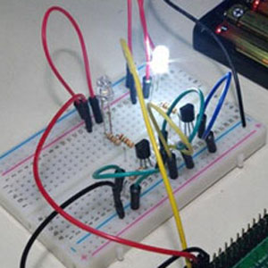
Now, let’s connect the transistor base to the Raspberry Pi GPIO. First, let’s think about the experiment and use a breadboard.
![]()
The rest is a program, but you can use the previous one as it is in Scratch. Of course, if you replace the GPIO pins, you should also change the number in the program.
Basically, declare the use of GPIO, set the pin output, input, etc., and then output ON (Hi) or OFF (Low). Since a positive input is applied to the base of the transistor by the ON (Hi) output, switching between the collector and the emitter turned on, lights up the LED.
PullUp and PullDown may be described in the program, but they’re not necessary here because 10kΩ is attached to the base of the transistor as a pull-down resistor. In other words, it corresponds to the hardware side.
How do you make this blink? That’s not difficult because you can control ON (Hi) output or OFF (Low) output by using the program. If you think about it, the first output is OFF (Low), then ON (H) is output, and the 1-second state is maintained, OFF (Low) output, this is also maintained for 1 second, and ON (Hi) output then repeated. What you have here is what we call a blinking/flashing LED. The example at Scratch is the one mentioned above.
Now that we’ve made our LED lights flicker, let’s try controlling multiple LEDs. This is how you can make two LED lights blink alternately. The connection uses two GPIOs, each driving an LED with a transistor.
![]()
I just made these two transistor drive circuits. The circuit is simple, but if you assemble it on a breadboard, the wires will be complicated, so pay close attention to the wiring. This is how the Scratch program works.
I use GPIO3 and GPIO4. 4 turns on first, 4 turns off after 1 second, then turns on 3 immediately, turns off after 1 second, and so on. Repeat 10 times, but if you want to repeat all the time, you should use the “all” block.
With this application, the number of LEDs can be increased by the available GPIO, four or 10 pieces. Not only can they flash in a consecutive order, but they can flash all at once, or even in the reverse direction, depending on the program you use.
How do you use this?
By the way, the biggest problems are the experiment, the practice of programming, and the training of electronic work for the LED flashing or flashing. The biggest problem is how to use this. Of course, it’s also good to use a Christmas tree or illumination. However, lighting doesn’t just mean being shiny, but there’s a variety of modeling elements involved, such as casting shadows, mixing colors, reflection and refraction, spectroscopy, and polarization.
You can also create an artistic work using light, depending upon the device.
In my case, this is the kind of work I’ve made.
Let the dancing Minowa dance(2010)(C)Naomi Ito
This part of the device lights up six LEDs in order. Here, the shadows of the six Minowa are projected onto the wall by LED light, but each shadow is projected in the same location, so that the shape of the shadow = the body pose. In other words, the shadows are expressed as animation.
From the stationary terracotta modeling and the title “Dancing Minowa,” it was made into an expressive piece of art using modern technology. It’s also a work that took a long amount of time to do.
The basis to all of this are the flashing LED lights, however as you can see, there is so much more you can do when you know how to apply them. Naturally, you don’t necessarily have to make something as artistic as this all the time, but it’s fun to get creative once in a while, isn’t it?
Electronic work is fun, but what else can you do besides building equipment and mechanisms? How can you make it more interesting? When you consider the different applications and expressions you can use, you can make even more complex and interesting creations. And then from there, you can modify it even further.
 Using LEDs and Motors on Raspberry Pi: How to Handle Larger Currents
 Sensor Input Experiment Using Raspberry Pi
 Building Something Interesting Using Sensors
 What Is Current, Voltage, Resistors, and Ohm’s Law?
 Raspberry Pi WebIOPi IOT Part 3 – Programming Basics (Input/Output)
 Arduino: The Popular Microcontroller Board! Its History and to How to Use It


