![]()

Today we’re going to test six onboard sensors on Sense HAT! If you are not familiar with the Sense HAT, please feel free to check back the previous article: The Sense HAT Add-On Board For Raspberry Pi – Operating The LED Display!
We will continue to follow the tutorial on the Raspberry Pi official website this time. Continued from the last time, it is the start from Chapter 4!
The Sense HAT has an 8 × 8 RGB LED matrix, a five – button joystick and includes the following sensors:
As you can see, the Sense HAT comes equipped with six types of sensors. Let’s try to acquire some data using these sensors!

Figure 1
First, let’s start with pressure, temperature and humidity sensors! These sensors are located on the right side of the Sense HAT. The humidity sensor is labeled “HUMIDITY” and below it is the atmospheric pressure sensor, labeled “PRESSURE”. The temperature seems to be read from the humidity sensor.
There’s a function for each sensor so the values can be acquired very easily!
Gets the current temperature in Millibars from the pressure sensor.
Get_temperature_from_humidity
Gets the current temperature in degrees Celsius from the humidity sensor.
Gets the current pressure in Millibars from the pressure sensor.
Gets the percentage of relative humidity from the humidity sensor.
Let’s use the sample code to get the values:
Env.py
|
1 2 3 4 5 6 7 8 9 10 11 12 13 14 15 16 17 18 19 20 21 |
from sense_hat import SenseHat sense = SenseHat() while True: t = sense.get_temperature() p = sense.get_pressure() h = sense.get_humidity() t = round(t, 1) p = round(p, 1) h = round(h, 1) msg = "Temperature = %s, Pressure=%s, Humidity=%s" % (t,p,h) sense.show_message(msg, scroll_speed=0.05) |
There wouldn’t be a problem even if you remove it from the command line, but if you forcibly terminate it while it’s running the LED display may stay on. (It does not turn off automatically; the state at the moment of termination is maintained). It’s recommended that you write a program that does not become an infinite loop or remove it from IDLE.
As shown in the above video, a character string “Temperature = 33.4, Pressure = 1010.8, Humidity = 33.8” is displayed on the LED matrix. These are the result I obtained: Temperature 33.4 °C; atmospheric pressure 1010.8 hPa; humidity 33.8%.
The temperature exceeded 30 degrees due to the heat generated by the Raspberry Pi. Although it’s quite different from the actual temperature, it seems to be useful for countermeasures against thermal runaway (as a measure of the main body temperature).
Scrolling_env.py
|
1 2 3 4 5 6 7 8 9 10 11 12 13 14 15 16 17 18 19 20 21 22 23 24 25 26 27 28 29 |
from sense_hat import SenseHat sense = SenseHat() while True: t = sense.get_temperature() p = sense.get_pressure() h = sense.get_humidity() t = round(t, 1) p = round(p, 1) h = round(h, 1) if t > 18.3 and t < 26.7: bg = [0, 100, 0] # green else: bg = [100, 0, 0] # red msg = "Temperature = %s, Pressure=%s, Humidity=%s" % (t, p, h) sense.show_message(msg, scroll_speed=0.05, back_colour=bg) |
The code above warns you of abnormal temperature on the International Space Station. The temperature value will show in green background when there is no problem (18.3 to 26.7 ° C) and red background in case of abnormality. In the video above, the temperature sensor indicates the value of 34.2 degrees so it’s shown in the red background.

Figure 2
Next to the humidity and pressure sensors there is an “Inertial Measurement Unit (IMU: Accelerometer, Gyroscope, Magnetometer)”.
A gyroscope is a spinning wheel or disc in which the axis of rotation is free to assume any orientation by itself. (It’s an instrument or device that detects the angle (attitude), angular velocity or angular acceleration of an object.)
An accelerometer is a device that measures proper acceleration. (A compact accelerometer (acceleration sensor) is fabricated using MEMS technology. MEMS accelerometers are used for automotive airbags, car navigation inclinometers, game controllers, etc.)
Acceleration, in physics, is the rate of change of velocity of an object with respect to time. An object’s acceleration is the net result of any and all forces acting on the object, as described by Newton’s Second Law. Accelerations are vector quantities (they have magnitude and direction).
A magnetometer is an instrument that measures magnetism—either magnetization of magnetic material like a ferromagnet, or the direction, strength, or the relative change of a magnetic field at a particular location.
I find angular velocity, angular acceleration, and acceleration pretty difficult concepts to grasp. The angular velocity describes the speed of rotation; the angular acceleration is the rate of change of the rotation speed (angular velocity); and the acceleration is the rate of change of the speed with direction (velocity).
In regards to the magnetic field, let’s look at how a compass works in the Sense HAT. For now, I have no idea how it is used but let’s try running a sample code.
First, I will use the gyroscope to acquire the orientation of the Raspberry Pi. To handle this sensor you need to understand the following three terms: Pitch, Roll, and Yaw.
Aircraft principal axes – Wikipedia
An aircraft in flight is free to rotate in three dimensions: pitch, nose up or down about an axis running from wing to wing; yaw, nose left or right about an axis running up and down; and roll, rotation about an axis running from nose to tail.
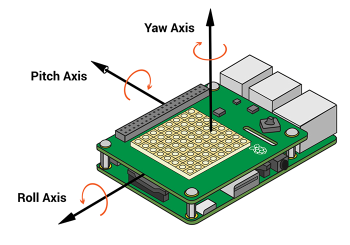
Figure 3
Above picture shows the axes in the Sense HAT.
Calls get_orientation_degrees above.
get_orientation_degrees
Gets the current orientation in degrees using the aircraft principal axes of pitch, roll and yaw.
The get_orientation function obtains how much the Raspberry Pi (Sense HAT) is inclined/tilted with respect to the horizontal plane as a numerical value.
These values are returned in Python’s dictionary. In other languages, it’s similar to an associative array.
Code-Example
|
1 2 |
pitch, roll, yaw = sense.get_orientation().values() print("pitch=%s, roll=%s, yaw=%s" % (pitch,yaw,roll)) |
Method for assigning values to each of the three variables is described on the official websitehere. I’m not entirely familiar with multiple variable assignment..
Code-Example
|
1 2 |
orientation = sense.get_orientation() print("p: {pitch}, r: {roll}, y: {yaw}".format(**orientation)) |
The code below (API Reference) shows a method to keep the dictionary as is and set variable individually to the output.
Code-Example
|
1 2 |
orientation = sense.get_orientation() print("p: %s, r: %s, y: %s" % (orientation["pitch"],orientation["roll"],orientation["yaw"])) |
Although the code becomes longer, it’s more easier to understand what’s going on, even for Python beginners.
Orientation2.py
Code-Example
|
1 2 3 4 5 6 7 8 9 10 11 12 |
from sense_hat import SenseHat import time sense = SenseHat() while True: orientation = sense.get_orientation() p=round(orientation["pitch"], 0) r=round(orientation["roll"], 0) y=round(orientation["yaw"], 0) print("p: %s, r: %s, y: %s" % (p,r,y)) time.sleep(1) |
I tried to tilt the Raspberry Pi in various directions while outputting the values of Pitch, Roll and Yaw at 1 second intervals. You can see that the values are changing as shown in the video above. If you rotate the Raspberry Pi side to side to turn it over, the value of Pitch changes. If you turn it upside down, the value of Roll will change, and if you rotate it horizontally, Yaw will change.
I’ve noticed that the value change slightly even if I’m not moving the Pi. Maybe it’s due to something in the surrounding that’s causing the values changing…?
Gets the raw x, y and z axis accelerometer data.
Acceleration.py
Code-Example
|
1 2 3 4 5 6 7 8 9 10 11 12 13 14 15 |
from sense_hat import SenseHat sense = SenseHat() while True: acceleration = sense.get_accelerometer_raw() x = acceleration['x'] y = acceleration['y'] z = acceleration['z'] x=round(x, 0) y=round(y, 0) z=round(z, 0) print("x=%s, y=%s, z=%s" % (x, y, z)) |
There’s another way to get x, y, z values, as shown in the above example code. It looks like it’s utilizing an acquisition method using the accelerometer. You can see a change in values when tilting the Raspberry Pi in the video above.
I can understand that the orientation can be acquired with a gyroscope, but the orientation can also be acquired with an accelerometer?
What is accelerometer? – atmarkIT
Accelerometer also detects the acceleration in the direction of the ground due to gravity, and the acceleration that can be obtained from the acceleration sensor is always the resultant force of acceleration applied to the device by the user and gravitational acceleration.
Acceleration detected by the accelerometer can be acquired as a component of each spatial axis in a three-dimensional space centered on the device as shown below.

We actually went over accelerometers in smartphones in our previous tutorial, Using Arduino with Parts and Sensors – Accelerometer Part 1.
Although it’s not published in the official Raspberry Pi site, I decided to try acquiring data with the magnetic sensor as well!
Calls set_imu_config to disable the gyroscope and accelerometer then gets the direction of North from the magnetometer in degrees.

Figure 5
Figure 5 shows the values obtained at 1-second intervals. I was able to obtain those values but what on earth do these numbers mean?! Even though there was a change in the direction, I did not see much change in the numbers. Maybe something nearby is interfering with the sensor? (If you were successful in obtaining the data, please share with us how you did!)
Astro Pi: 3D-Print Your Own Flight Case – Raspberry Pi
So I tried to make a case that’s similar to Astro Pi flight case!
There are different versions for the flight case. I 3D printed total 4 parts, SECTION_1-4.
3D Printed Astro Pi Flight Case | Raspberry Pi Learning Resources
Please check out the above link for more details on how to make the case. The required parts, connection method, and assembly method are explained in detail.

Figure 6
Here is the case I made! First, I printed SECTION_2 and SECTION_3 to put together the main body. It did not fit snugly without using the screws, as you can see the little gaps…
At first, I thought the case was huge, but it actually fits the main body and the Sense HAT quite nicely. There was also a space to attach the buttons. Oh, you can also place the camera, of course!

Figure 7
Next, I printed SECTION_1 and SECTION_4. I changed the color of the lid and the heat sink for better presentation. There was a minor error in 3D printing and I was not able to perfectly align/assemble the case…

Figure 8 The assembled flight unit / @Raspberry Pi
Just make sure you follow the steps as described on the official website. You’ll be able to put together a nice looking flight case as shown in Figure 8. Also, make sure to use the right material for the case to minimize any distortions.
We were able to acquire values from Sense HAT’s six onboard sensors!
As for the temperature sensor, if you connect the Raspberry Pi body and Sense HAT separately, it looks like it’s possible to avoid the heat problem we discussed above (i.e. heat from the main body affecting the real data).
Next time we’ll go over how to use Sense HAT joystick as inputs!
 The Sense HAT Add-On Board For Raspberry Pi – Sense HAT Emulator
 The Sense HAT Add-On Board For Raspberry Pi – Operating The LED Display
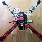 DIY Raspberry Pi Drone Part 3 – FPV Setup Guide
 DIY Raspberry Pi Drone Part 2 – Naza-M Lite Guide
 Raspberry Pi WebIOPi IOT Part 2 – Making a flashing LED button
 The Sense HAT Add-On Board For Raspberry Pi – Joystick


