![]()
This article was translated to English, and was originally published for deviceplus.jp.
In this article, we learn about the principles involved in electronic work and its foundations through simple works on Raspberry Pi. Teaching us today is Naomi Ito, a media artist and author known for her explanations on the “deeper mechanisms.” Continuing from the last article about blinking LED lights, we will learn how to handle slightly larger currents for operating motors on Raspberry Pi.
Table of Contents
Last time, I tried to turn on the LED using the GPIO on Raspberry Pi, but because I had to be careful about the flow of electricity going into the electronic parts, I talked about resistors for limiting the currents to LED.
We talked about how we could calculate this with Ohm’s law. Now that there are so many LEDs on the market, let’s take a closer look at the rating tables and data sheets. In circuit design, it’s important to pay special attention to the voltage and currents.
If the voltage is too high, or if the current is overflowing, there’s a chance that it’ll break. It would be a real shame for something to break that you’ve worked so hard on.

It can burn, or even explode
If that happens, don’t give up (I’ve also experienced it). Treat it as a good lesson learned. However, I can’t advocate for “actively breaking” our work! In addition to work breaking, parts may explode or generate excessive heat, causing injuries and even fires.
Let’s take a closer look and talk a bit about the capacity of LEDs.
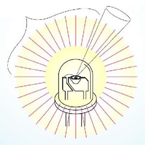
Looking inside this bullet-type LED, it looks like this.

inside the bullet-type LED
The part that actually emits light is a small chip in the middle dish. The dish becomes a reflector, and the tip of the package is in the shape of a lens, so a lot of light rises up.
Depending upon the product, a plate may be attached to the anode side, so it cannot always be determined by the shape of the internal lead frame.
There are two kinds of brightness displays: Candela and Lumen.
If you look at the data sheet of the LED, you can see the notation “cd (candela)” and “lm (lumen)” in the unit of brightness. Both of them indicate brightness numerically, meaning that the larger the number, the brighter it is. However, the meaning of each is actually different.
How many light beams are emitted from the light source when the light emitted from the light source is considered to be a line and is defined as a bundle of light? This is called “lm (lumen).” In the actual shape of an instrument, light doesn’t leak behind, or it may be directed in one direction because of the lens and reflector. Displaying the luminous flux per unit angle is called luminosity, and it’s expressed as “cd (candela).”
In addition, you may hear about the brightness unit known as “lx” (Luxe). This represents the brightness of the surface that was hit. That should cover the basics.

By the way, on this often-seen bullet-type LED, light somewhat leaks from the back due to reflection inside the resin packaging. However, if there’s an aluminum substrate that also serves as thermolysis on the back of the power LEDs, the light won’t leak behind those. If you look at the component parts, the brightness notation of power LED may be a notation that classifies these product structures as consisting of many lm.
Color temperature
Color temperature is displayed as “K” (Kelvin) units. For example, when an iron nail is blown with a stove, it gradually becomes red. It’s emitting a red light. This is called heat radiation; the color turns yellow as the temperature rises. Quantitatively, this captures the change in color due to the temperature and notates the color.
In particular, white LEDs range from pale white to those that appear to be orange, which are called light bulb colors. The higher the color temperature, the paler the white will be.
Wide angle, narrow angle
Although expressed as a half-angle, it indicates the spread of light. This depends upon the structure of the package lens and the lead frame. For example, an LED with the same brightness is brightest in the center at a narrow angle, and the surroundings rapidly darken. However, at a wide angle, the light spreads widely so that it can be evenly brightened to some extent.
Choosing what suits your work
Now, you probably know a lot about LEDs. After that, you have to choose the LED that best suits your purpose.
For example, the brighter the work, the better. Of course, this will also depend upon your budget, but if you want to illuminate something, it is better to be bright. Meanwhile, if you’re using it as a display, it can be dark. If you look at a dark seven-segment LED at night, the letters will appear blurred out, and it’ll probably be difficult to read the numbers.
Now, let’s go about talking about Raspberry Pi.
How can I control anything other than LEDs with a Raspberry Pi? For example, what about devices that require a larger current than LEDs, such as motors?
Speaking of famous DC motors for model work, let’s talk about Mabuchi. Take the standard FA-130RA as an example.

Looking at the performance table written on the package, it’s labeled as 1.5V-3V, 500mA. Since it’s often used for models and toys, it seems that the voltage setting is based on dry cell power.

The motor obtains rotational motion by the force received by the coil in the magnetic field. In addition, the coil itself generates reactance that cannot be seen, such as reactance, so it may be difficult to imagine what the flow of electricity is like.
For now, you can think of it as 3V500mA on the package.
500mA means that if we want to use the transistor 2SC1815 as an example, it has a current value exceeding the current value because the current flowing through the collector is up to 150mA. What should we do?
There are several ways to do this.
What you need to handle large currents
For example, you can use a motor drive expansion board or motor driver IC. These depend upon the function of the board and IC, so it may be convenient depending upon how you use forward, reverse, and brake.
There’s another way to use a relay. Since the relay is a mechanism that contacts the coil = electromagnet, depending upon the product, it may be necessary to drive the coil part with a transistor, etc., just as with LEDs. It’s the same as a switch, so outlets (100V) can be turned on and off within the rated range.
However, since it has physical contacts, the service life depends upon the frequency of use. There are also SSRs (Solid State Relays) that consist of semiconductors with the same usability.

The picture shows a relay with a transparent package (you can see the coil inside)
I tried a couple of different methods. There may still be devices that I don’t know about, and I think it’s better to choose the one that best suits your work.
Here, let’s go back to the basics and drive with transistors.
However, I chose the 2SC2655L to pass a large current. This allows the collector current to flow up to 2A. Is that not enough to drive this DC motor? You can connect with the same circuit as the LED.

The circuit turns a motor connected to the collector through a 1kΩ resistor from GPIO to the base of the transistor.

Assembling with a breadboard will look like this.

I used the same program on Scratch as before. In other words, on devices such as LEDs that have changed, the same program can be used. However, the movement is quite different. This is because the motor moves like a LED and doesn’t stop.
For the time being, I tried the following shapes. Declare GPIO, set pin 4 to output, and then repeat ON-OFF 10 times every second.

Since the motor has a fan, let’s assume that it’s used like a fan. It’s a fan experimental device so that you can change it on a breadboard.
Turning on the motor can be done just by switching on either ON or OFF.
So, how can we control the rotation speed?
Some modern fans send a gentle breeze intermittently, such as “soft breeze mode,” so let’s try to reproduce this.
Operating with PWM
There’s a frequently used method called PWM used for digital control.
This is translated as “pulse width modulation,” but it’s essentially a method for changing the ON and OFF state of one cycle via pulse width in the fast signal cycle. If the ON state is long (Fig. 2), the amount of electricity that flows as a result will be larger than the short state (Fig. 3 below). In other words, DC motors are faster, and vice versa.

Now, at Scratch, let’s try it together like this. Declare GPIO, set pin 4 to PWM output, create a variable “power4,” and set it to 0 as the initial value.
Output “power4” to GPIO4 in the computation block. You can also control the air volume by dragging the slide button with the variable display on the screen display slider. At this time, if you set the maximum value of the slider to “1023,” it’ll turn fully.

Oops, let’s try automatically stopping the wind, letting it blow, and repeat. Also, let’s try turning on the LED.
Just like that, through PWM, it’ll get brighter and darker while the fan rotates accordingly.
The circuit should look like this.

The breadboard would be like this.

Scratch should be like this.

The variable part is raised, and the state is kept at 5 seconds for the maximum value, and then the variable is lowered and kept at 0 at 5 seconds. LED brightness follows this.
It looks like we’ve finally made something resembling an experimental device.
What did you think? Now, we have a cool fan that could really help for those scorching summer days.
Even as a media artist, it’s times like this that I feel like an engineer. Making such a device happens to do that to you, at least when looking at it from the outside.
Today, we were able to make something resembling what engineers do daily. For the next article, we’ll be building a sensor while thinking more deeply about the mechanisms and assembly.
After all, works of art can only be made if you know the characteristics of the paint and how to use it.
 Learning About Ohm’s Law, GPIO and Transistors with Flashing LEDs on Raspberry Pi
 What Is Current, Voltage, Resistors, and Ohm’s Law?
 Sensor Input Experiment Using Raspberry Pi
 Building Something Interesting Using Sensors
 Arduino – Sketch, Taking a Look at Programs
 Making an LED Light up with Raspberry Pi Before Making It Blink