![]()
Click here to read Part 1 of this article >
Step #10: Attach ESCs to arms
Now that the core of the frame has taken shape you can begin to attach components to the arms. You can mount the each ESC under the arm with zip-ties as pictured below.

Figure 16: ESCs zip-tied to the frame’s arm
Step #11: Bolt motors to arms
Mount a motor at the end of each arm that spins in the direction indicated in the diagram below. The direction the motor is intended to spin is indicated on the side of the motor. For example, mount a counter-clockwise motor on the back left, and a clockwise motor on the front left.

Figure 17: Numbering of motors assumed by NAZA / Ⓒkenstone6.net
Step #12: Connect motor leads to ESC

Figure 18. The three motor wires are connected to the ESC, like in the image above
Connect the three wires coming from each motor to the three holes on the front of the adjacent ESC. At this point in time it doesn’t matter what order the wires are connected. (If necessary, we’ll correct the order in Part 2).
Step #13: Attach LED module to flight controller and arm
The NAZA-M Lite comes with a small module that is both an LED indicator (e.g. warns of low battery, displays good GPS lock) and USB interface to a PC. The LED module is pictured below. Attach the end of its long cable to the slot on the back of the NAZA-M Lite labeled “LED”. We will use the USB interface in Part 2 to configure the flight controller. I mounted the module onto the side of the back-left arm with hot glue.

Figure 19: NAZA-M Lite LED indicator on the back arm
Step #14: Mount GPS
The GPS provided with the NAZA-M Lite comes with a post to mount it on. By mounting the GPS upon its post you increase the distance of the motors and ESCs to the GPS, decreasing the likelihood of electromagnetic interference. The GPS post has three parts: the bottom which has four legs, the long thin rod that fits in snugly with the parts above and below it with a little glue, and the top flat part that the GPS actually mounts to. I mounted the GPS post to the back-right corner of the frame. The terminating end of the GPS cable has a connector identical to that of the LED module; the GPS cable is connected adjacent the LED module, in a slot labeled “EXP.”

Figure 20: GPS mounted on top of frame
Step #15: Install Raspberry Pi

Figure 21: Raspberry Pi mounted on bottom of frame
The most convenient spot I found to mount the Raspberry Pi is on the bottom plate between where the legs attach to the frame (see above picture). I oriented the GPIO pins facing down and the USB port facing out the side opposite the battery connector. The Raspberry Pi does not make flat contact with the bottom plate so double sided tape would not work well; instead I used hot glue to secure the corners to the legs.
Step #16: Install voltage regulator
While we are working on the bottom of the quadcopter the voltage regulator can be glued to the bottom plate directly underneath where its wires are soldered to the power distribution board.

Figure 22: The voltage regulator is the small black rectangle between the two white legs
Step #17: Install Raspberry Pi Camera
Since the purpose of the Raspberry Pi camera is to provide a live view of what the quadcopter is directed towards, it should be mounted on the quadcopter’s front. I hot glued a small piece of cardboard to the front of the frame between the two arms and then glued the Raspberry Pi camera to the cardboard (see the picture below; my camera has a fisheye lens so your camera may look slightly different).

Figure 23: Raspberry Pi Camera used for First Person View (FPV) from the quadcopter is in the top half of the image. The lower half shows the top of the gimbal which we will install shortly.
Your Raspberry Pi camera should already come with a ribbon cable connected. The other end of the ribbon cable must be connected to the Raspberry Pi on the quadcopter’s bottom. First slide the ribbon cable behind the cardboard and through the hole directly below; then give a slight twist to the ribbon cable so that the exposed metal on the cable is facing the opposite direction of the USB port.

Figure 24: Camera connection to Raspberry Pi
To install the ribbon cable in the Raspberry Pi gently pull open the white cover on the black connector labelled CAMERA (between the HDMI and Audio out/composite video out ports). Insert the cable as much as you can making sure that it is evenly inserted. While holding the cable, lock the cable in place with the white piece we opened earlier.
Step #18: Power flight controller and Raspberry Pi from voltage regulator

Figure 25. The brown and red wires from the regulator soldered to the positive and negative wires of a micro USB cord
The voltage regulator we installed earlier provides a convenient 5V output to power the flight controller. We can take advantage of this 5V supply to power the Raspberry Pi. To do so I cut the red and brown wires from the voltage regulator’s PWM cable and soldered them into the positive (red) and negative (black/brown) wires, respectively, of a micro USB cord. Make sure you solder the end of the PWM cable to this new wiring harness as well! Otherwise you will have no way to power the flight controller. Then simply plug the micro USB cord into the Raspberry Pi to power it.
To bring power to the flight controller connect the PWM cable from the voltage regulator to the X3 slot on the back of the flight controller.
Step #19: Install vibration isolation gimbal mount

Figure 26: Side view of the gimbal after installing rubber balls
The gimbal’s first step against removing vibrations and rotation of the camera is through six vibration isolation rubber balls that connect the gimbal to the quadcopter’s frame. To install the rubber balls you must fit them into the small holes on the lower gimbal and then fit the top of the balls into the top plate of the gimbal. To prevent the gimbal from coming off in flight (if the vibration isolation balls happen to fail) I looped one zip-tie through a hole on each side of the gimbal. When you do so it should look like the image above.
Step #20: Bolt the gimbal to the front extension of the frame

Figure 27: Top view of gimbal with bolts installed
To reduce the chance of one of the quadcopter’s legs coming into the frame of the gimbal during a rapid turn I decided to bolt the gimbal to the front extension of the frame (e.g. mounting the gimbal below the center of the frame would increase the chances of legs appearing in video). To do so I put the head of the M3 bolt (you may also use M4 size nuts and bolts, however you will need to increase the size of the two back holes a small amount to fit the larger bolts) into the two holes on the gimbal’s top plate and another two M3 bolts in the corners of the wide open spot (see above for where I positioned the bolts; notice that the small arrow represents the front of the gimbal).
I then tightened a nut on each bolt such that they were secured with the gimbal. To attach the gimbal to the frame I slid the bolts into the two open rows on the front extension of the frame and top them off with one more nut each (see below for what the gimbal looks like when it is bolted to the front of the frame).

Figure 28: Front view showing Raspberry Pi Camera and Gimbal
Step #21: Create a separate extension cable for the battery connector that is soldered to the gimbal power cable
In order for the FeiYu Tech Mini-3D Gimbal to function it must receive power from the battery. I created an extension cord for the battery connector and cut off the JST connector from the gimbal power cord and then soldered the power cord to the extension cord. The extension cord consists of a male T-Connector on one end, a female T-Connector on the opposite end, and the gimbal power cable soldered in the middle. Using an extension cord and not soldering the gimbal power directly to the power distribution board you are able to remove the gimbal from the frame for easier transport or if you wish to fly without the gimbal.

Figure 29: How the gimbal wires (small red and black wires above) are soldered to the extension cord.
Step #22: Mount the camera in the gimbal

Figure 30: Xiaomi Yi Camera installed in gimbal
The Xiaomi Yi camera used in this project is slightly bigger than the GoPro for which this gimbal was designed for. But if you screw in the bottom bolt of the brace first and then the top part you can still fit the Xiaomi Yi camera without any modifications to the gimbal.
Step #23: Install phone mount on transmitter

Figure 31: Phone mount installed on back of transmitter
The particular procedure to install your phone mount may vary but to install mine I simply peeled a protective layer off a large piece of double sided tape on a circle slightly larger than the suction cups mount. I used the doubled sided tape to firmly attach the circle to the back of the transmitter. This circle then provided an easy way to secure the suction cup and thus the phone holder to the transmitter. After sticking a metal plate (provided with the phone mount) to the back of my phone’s case I bent the flexible arm so I could see the phone’s screen while holding the transmitter normally. See the picture above for a side view of my phone mount.
The magnet on the end of the phone mount magnetically holds your phone to the mount with the metal plate mentioned earlier.
Step #24: Install transmitter batteries
Simply take the battery cover off the transmitter and install the AA batteries in the battery case. Then plug the small connector from the battery case into the transmitter following the polarity instructions printed near the two pins (as you can see in the picture below from within the transmitter’s battery bay).

Figure 32: Battery connector for transmitter

Figure 33. Side view of the quadcopter

Figure 34. Bottom view of the quadcopter (pictured without Raspberry Pi)
Congratulations! You have just assembled an Aerial Video quadcopter. Currently your quadcopter is not ready for flight. In Part 2 & 3, we will configure the quadcopter’s software, learn how to fly the quadcopter, and do some test flights. Check back for the next phase of this build in the the coming month. Stay tuned!
 DIY Raspberry Pi Drone: Mechanics – Part 1
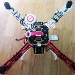 DIY Raspberry Pi Drone Part 3 – FPV Setup Guide
 DIY Raspberry Pi Drone Part 2 – Naza-M Lite Guide
 DIY Smart Picture Frame & Calendar Using Raspberry Pi 3 – PART 1
 How to Build a DIY Drone from Scratch Part 1: Building a Cheap DIY Drone
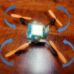 How to Build a DIY Drone from Scratch Part 2: Using Arduino Nano as a Flight Controller


